×
ToyotaParts- Hello
- Login or Register
- Quick Links
- Live Chat
- Track Order
- Parts Availability
- RMA
- Help Center
- Contact Us
- Shop for
- Toyota Parts
- Scion Parts
My Garage
My Account
Cart
OEM 2003 Toyota Highlander Rack And Pinion
Steering Rack And Pinion- Select Vehicle by Model
- Select Vehicle by VIN
Select Vehicle by Model
orMake
Model
Year
Select Vehicle by VIN
For the most accurate results, select vehicle by your VIN (Vehicle Identification Number).
1 Rack And Pinion found

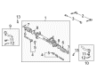
2003 Toyota Highlander Gear Assembly
Part Number: 44250-48070$871.10 MSRP: $1276.61You Save: $405.51 (32%)Ships in 1-3 Business DaysProduct Specifications- Other Name: Gear Assembly, Power Steering; Rack and Pinion Assembly; Steering Gearbox; Rack & Pinion; Steering Rack; Short Rack; Gear Assembly, Power Steering(For Rack & Pinion)
- Replaces: 44200-48070
- Part Name Code: 44250
- Item Weight: 20.50 Pounds
- Item Dimensions: 49.7 x 10.6 x 6.8 inches
- Condition: New
- Fitment Type: Direct Replacement
- SKU: 44250-48070
- Warranty: This genuine part is guaranteed by Toyota's factory warranty.
2003 Toyota Highlander Rack And Pinion
Looking for affordable OEM 2003 Toyota Highlander Rack And Pinion? Explore our comprehensive catalogue of genuine 2003 Toyota Highlander Rack And Pinion. All our parts are covered by the manufacturer's warranty. Plus, our straightforward return policy and speedy delivery service ensure an unparalleled shopping experience. We look forward to your visit!
2003 Toyota Highlander Rack And Pinion Parts Q&A
- Q: How to Overhaul a Rack and Pinion Steering Gear on 2003 Toyota Highlander?A: Place a new claw washer before fixing the rack ends in position but only maintain them briefly to align their claws with the rack and pinion grooves. Use Special Service Tool: 09922-10010 to guide the rack end installation with precision torque at 49.5 Nm (505 kgf-cm, 37 ft. lbs.) when using the tool to stabilize the rack with a torque wrench staged at 345 mm (13.58 inch). Apply a brass bar and hammer for staking the claw washer but avoid hitting the rack and pinion and perform this process again on the additional rack end. The inspection of the rack and pinion hole should be followed by rack boot No.2 installation and rack boot No.1 removal through the same process. Use Special Service Tool: 09521-24010 to tighten rack boot No.2 clamp until it reaches a clearance of 3.0 mm (0.118 inch) while avoiding boot damage. Install rack boot No.1 clamp in the same manner. Preform the operation with pliers while installing the two boot clips. To install the tie rod assembly begin by screwing the lock nut and tie rod assembly LH onto the rack end until the matchmarks become aligned and then torque the lock nut after toe-in adjustment followed by the right-hand side assembly. Position the left turn pressure tube's two new O-rings coated with power steering fluid on the assembly and employ Special Service Tool: 09023-38200 to install them to the rack and pinion assembly while ensuring the tool remains parallel to the torque wrench. Torque the assembly to 12 Nm (120 kgf-cm, 9 ft. lbs.). Attach another O-ring to the right turn pressure tube then mount the tube to its rack and pinion assembly using Special Service Tool: 09023-38200 and torque the connection to 12 Nm (120 kgf-cm, 9 ft. lbs.). The power steering rack and pinion assembly requires two bolts and nuts which should be torqued to 70 Nm (715 kgf-cm, 52 ft. lbs.) before connecting the pressure feed tube assembly clamp with its bolt torqued to 9.8 Nm (100 kgf-cm, 87 inch lbs.). Use Special Service Tool: 09023-12700 to mount the pressure feed tube assembly to the rack and pinion with a torque of 22 Nm (230 kgf-cm, 16 ft. lbs.). Perform the return tube assembly installation in the same manner. The front stabilizer link assemblies require installation followed by torquing the LH side to 74 Nm (755 kgf-cm, 55 ft. lbs.) while using a hexagon wrench if needed. The steering intermediate shaft sub-assembly requires proper matchmark alignment before installing its bolt to 35 Nm (360 kgf-cm, 26 ft. lbs.) and applying the same torque to bolt A. Secure steering column hole cover No.2 while implementing the clamp to steering column hole cover No.1. Complete the assembly of tie rod LH by torquing the nut to 49 Nm and adding a new cotter pin while you may need to tighten the nut more. The second procedure involves installing the front wheel while torquing it to 103 Nm (1,050 kgf-cm, 76 ft. lbs.). The maintenance process concludes by draining power steering fluid then inspecting leaks while installing both steering wheel components and SRS warning light and front wheel alignment along with steering wheel center point adjustment.
Related 2003 Toyota Highlander Parts
 2003 Toyota Highlander Steering Wheel
 2003 Toyota Highlander Power Steering Hose
 2003 Toyota Highlander Power Steering Pump
 2003 Toyota Highlander Ignition Switch
 2003 Toyota Highlander Power Steering Reservoir
 2003 Toyota Highlander Shift Interlock Solenoid
 2003 Toyota Highlander Steering Angle Sensor
 2003 Toyota Highlander Steering Column
 2003 Toyota Highlander Steering Column Cover
 2003 Toyota Highlander Steering Shaft
 2003 Toyota Highlander Tie Rod End
 2003 Toyota Highlander Universal Joint