×
ToyotaParts- Hello
- Login or Register
- Quick Links
- Live Chat
- Track Order
- Parts Availability
- RMA
- Help Center
- Contact Us
- Shop for
- Toyota Parts
- Scion Parts
My Garage
My Account
Cart
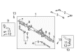
OEM 2004 Toyota Highlander Rack And Pinion
Steering Rack And Pinion- Select Vehicle by Model
- Select Vehicle by VIN
Select Vehicle by Model
orMake
Model
Year
Select Vehicle by VIN
For the most accurate results, select vehicle by your VIN (Vehicle Identification Number).
1 Rack And Pinion found

 Product Specifications
- Other Name: Steering Gearbox
- Part Name Code: 44200
- Item Weight: 12.10 Pounds
- Item Dimensions: 50.7 x 11.0 x 6.9 inches
- Condition: New
- Fitment Type: Direct Replacement
- SKU: 44200-48090
- Warranty: This genuine part is guaranteed by Toyota's factory warranty.
2004 Toyota Highlander Rack And Pinion
Looking for affordable OEM 2004 Toyota Highlander Rack And Pinion? Explore our comprehensive catalogue of genuine 2004 Toyota Highlander Rack And Pinion. All our parts are covered by the manufacturer's warranty. Plus, our straightforward return policy and speedy delivery service ensure an unparalleled shopping experience. We look forward to your visit!
2004 Toyota Highlander Rack And Pinion Parts Q&A
- Q: How to Overhaul a Rack and Pinion Steering Gear on 2004 Toyota Highlander?A: Begin the rack and pinion overhaul by checking the front center wheel before removing the front wheel. Use Special Service Tool 09628-62011 to detach the tie rod assembly LH before replicating the process for the tie rod assembly RH. Users should begin by fixing the steering wheel using a seat belt to stop rotation while they loosen bolt A to remove the clamp from the steering column hole cover No.1. Then users should separate the steering column hole covers before loosening bolt B. After marking the matchpoints on the steering intermediate shaft sub-assembly and steering link assembly, they should finally remove the bolt to disengage the steering intermediate shaft sub-assembly. The technician must break apart the front stabilizer link assemblies LH and RH before removing the two bolts of the front stabilizer bracket No.1 LH then stripping the stabilizer bracket No.2 and the stabilizer bar bush No.1. Perform the same procedure to detach the front stabilizer bracket No.1 RH. Disconnect the return tube assembly by employing Special Service Tool: 09023-12700 and a tube clamp removal from the pressure feed tube assembly followed by using this tool to remove the return tube assembly from the steering link assembly then remove the nut and return tube clamp. Complete the pressure feed tube assembly disconnect procedure in the exact fashion. Uninstall the power steering link assembly through removal of two bolts and nuts. Start by removing the tube clamp from the steering left turn pressure tube and then use Special Service Tool: 09023-38200 to disconnect it while removing the pair of O-rings. The same method must be applied to disconnect the steering right turn pressure tube. Smoothly attach the power steering link assembly with Special Service Tool: 09612-00012 and secure it with tape to shield it from harm. Start the tie rod assembly LH removal process by marking matchpoints then loosening the lock nut until the assembly can be extracted with the lock nut. For the tie rod assembly RH follow the same steps. First untie the steering rack boot clips along with steering rack boot No.2 clamp while being cautious to protect them from damage and then handle steering rack boot No.1 in the same manner. Proceed to remove both steering rack boots before extracting the rack and pinion end sub-assembly by unstaking the claw washer with a screwdriver and hammer and using Special Service Tool: 09922-10010 to remove the rack end RH and claw washer and the rack end LH and claw washer. Start rack guide removal by utilizing Special Service Tool: 09922-10010 to disassemble the spring cap lock nut after which Special Service Tool: 09631-10021 takes off the rack guide spring cap before extracting the compression spring and rack guide. You should employ Special Service Tool: 09616-00011 for power steering control valve shaft stabilizing during nut removal after applying vinyl tape to protect the oil seal on the spline. Then remove the rack housing cap with a 27 mm socket wrench while sequentially removing the dust cover and bolts and control valve and valve housing. Take out the power steering control valve, its gasket and oil seal followed by carefully removing the four control valve spacers. Special Service Tool: 09950-70010 (09951-07150), 09950-60010 (09951-00250) and a press enable users to remove the power steering control valve upper oil seal. To access the wire end on the cylinder end stopper follow with a clockwise rotation then reverse to free up the wire and stopper. To remove the power steering rack and the power steering rack bush start by detaching the rack bush with its oil seal through Special Service Tool: 09527-21011, 09612-24014 (09613-22011) for removing the oil seal before safely removing the O-ring. The power steering rack demands inspection for runout and wear while it must lie horizontally before deciding to replace the power steering link assembly for any runout exceeding 0.3 mm (0.0118 in.). Use Special Service Tool 09950-70010 (09951-07360) and 09950-60010 (09951-00290) along with a press to remove the power steering cylinder tube oil seal yet protect the rack housing interior from damage. Installation requires placing a new O-ring into power steering fluid before applying the fluid and expanding the new oil seal which receives fluid application prior to rack and pinion installation. The power steering cylinder tube oil seal requires power steering fluid treatment on its new lip before its installation through Special Service Tool: 09950-60010 (09951-00450, 09951-00250, 09952-06010), 09950-70010 (09951-07360) with correct installation direction. The inspection of the LH tie rod assembly requires mounting it in a vise and tightening the nut while rotating the ball joint stud before measuring the torque value and replacing the component unless it falls between 0.49 to 3.43 Nm (5.0 to 35.0 kgf-cm, 4.3 to 30.4 in.-lbf). Begin the procedure again for the tie rod assembly RH and install the rack and pinion by applying grease to the rack teeth ends after mounting Special Service Tool 09631-33010 and adding power steering fluid onto the tool as you install it to the rack housing before removing it.
Related 2004 Toyota Highlander Parts
 2004 Toyota Highlander Steering Wheel
 2004 Toyota Highlander Power Steering Hose
 2004 Toyota Highlander Power Steering Pump
 2004 Toyota Highlander Ignition Switch
 2004 Toyota Highlander Power Steering Reservoir
 2004 Toyota Highlander Rack and Pinion Boot
 2004 Toyota Highlander Shift Interlock Solenoid
 2004 Toyota Highlander Steering Angle Sensor
 2004 Toyota Highlander Steering Column
 2004 Toyota Highlander Steering Column Cover
 2004 Toyota Highlander Steering Shaft
 2004 Toyota Highlander Tie Rod End