×
ToyotaParts- Hello
- Login or Register
- Quick Links
- Live Chat
- Track Order
- Parts Availability
- RMA
- Help Center
- Contact Us
- Shop for
- Toyota Parts
- Scion Parts
My Garage
My Account
Cart
OEM 2008 Toyota Highlander Rack And Pinion
Steering Rack And Pinion- Select Vehicle by Model
- Select Vehicle by VIN
Select Vehicle by Model
orMake
Model
Year
Select Vehicle by VIN
For the most accurate results, select vehicle by your VIN (Vehicle Identification Number).
1 Rack And Pinion found


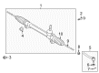
2008 Toyota Highlander Steering Gear
Part Number: 45510-0E030$610.16 MSRP: $894.21You Save: $284.05 (32%)Ships in 1-3 Business DaysProduct Specifications- Other Name: Gear Assembly, Steering; Rack and Pinion Assembly; Steering Gearbox; Gear Assembly
- Replaces: 45510-48010
- Part Name Code: 45510
- Item Weight: 12.90 Pounds
- Item Dimensions: 31.6 x 12.1 x 5.3 inches
- Condition: New
- Fitment Type: Direct Replacement
- SKU: 45510-0E030
- Warranty: This genuine part is guaranteed by Toyota's factory warranty.
2008 Toyota Highlander Rack And Pinion
Looking for affordable OEM 2008 Toyota Highlander Rack And Pinion? Explore our comprehensive catalogue of genuine 2008 Toyota Highlander Rack And Pinion. All our parts are covered by the manufacturer's warranty. Plus, our straightforward return policy and speedy delivery service ensure an unparalleled shopping experience. We look forward to your visit!
2008 Toyota Highlander Rack And Pinion Parts Q&A
- Q: How to install the power steering Rack And Pinion and related components on 2008 Toyota Highlander?A: Start the power steering rack and pinion installation by fixing the tie rod assembly LH to its corresponding spot on the steering rack end sub-assembly with matching marks in position as you adjust toe-in by torquing the lock nut. Then repeat these steps for fixing the tie rod assembly RH. Start by installing the power steering link assembly with 2 bolts and 2 nuts at the left side of the vehicle before tightening the bolt while the nut remains fixed. Use a torque of 70 Nm (713 kgf-cm, 51 ft-lbf) for the installation. Install both front stabilizer bar components together with their front No. 1 stabilizer brackets which should be installed to the left side followed by the right side. The procedure involves installing the engine-transaxle assembly after reattaching suction and discharge hoses sub-assemblies to both front axle assemblies LH and then RH. The left and right lower front suspension arms must be installed with correct torque of 49 Nm (500 kgf-cm, 36 ft-lbf) to secure the tie rod assembly to the steering knuckle while using a new cotter pin to provide additional nut-tightening. Repetition of this procedure applies to the tie rod assembly RH. Connect the steering intermediate shaft assembly through bolt installation while matching the marks then torque the bolt to 35 Nm (357 kgf-cm, 26 ft-lbf). Begin the process by inserting both front speed sensors followed by front axle hub nuts then adding the front stabilizer link assemblies to the vehicle. The front exhaust pipe assembly together with the front No. 3 exhaust pipe sub-assembly, center exhaust pipe assembly, and tail exhaust pipe assembly need installation. Fully tighten the propeller with center bearing shaft assembly for 4WD after performing initial temporary tightening and then connect all components including the engine wire transmission control cable assembly fuel tube sub-assembly various inlet and outlet hoses and finally install both No. 1 and No. 2 radiator hoses. Union assembly requires connection to air control valve hose before joining the No. 1 fuel vapor feed hose and engine moving control rod as well as the No. 2 engine mounting stay RH, reservoir bracket, brake master cylinder reservoir assembly, air cleaner bracket, battery, air cleaner case sub-assembly, air cleaner filter element sub-assembly, air cleaner cap sub-assembly, No. 1 and No. 2 air cleaner inlets and vacuum hoses. Place the outer cowl top panel assembly together with windshield wiper motor, links, ventilator louver assembly, front wiper arms and blades for both sides and front wheels before torquing to 103 Nm (1050 kgf-cm, 76 ft-lbf). Engine oil and engine coolant and automatic transaxle fluid need to be added after checking the fluid levels. Perform leak inspections for fuel, engine oil, coolant and exhaust gas while also checking the shift lever position and ensuring direct front wheel alignment and inspecting wheel alignment adjustments. The technician must inspect ignition timing together with engine idle speed as well as CO/HC levels and throttle body assembly operation. The technician should install front fender apron seals LH and RH, front fender liners LH and RH, and front fender moulding sub-assemblies LH and RH. To complete the checklist install the floor under cover LH followed by No. 2 engine under cover then No. 1 engine under cover and the engine under cover assembly after which install the V-bank cover sub-assembly and double-check the ABS speed sensor signal along with resetting the memory.
Related 2008 Toyota Highlander Parts
 2008 Toyota Highlander Steering Wheel
 2008 Toyota Highlander Ignition Switch
 2008 Toyota Highlander Rack and Pinion Boot
 2008 Toyota Highlander Shift Interlock Solenoid
 2008 Toyota Highlander Steering Angle Sensor
 2008 Toyota Highlander Steering Column
 2008 Toyota Highlander Steering Column Cover
 2008 Toyota Highlander Steering Gear Box
 2008 Toyota Highlander Steering Shaft
 2008 Toyota Highlander Tie Rod End
 2008 Toyota Highlander Wiper Switch