×
ToyotaParts- Hello
- Login or Register
- Quick Links
- Live Chat
- Track Order
- Parts Availability
- RMA
- Help Center
- Contact Us
- Shop for
- Toyota Parts
- Scion Parts
My Garage
My Account
Cart
OEM Toyota Highlander Power Steering Pump
Power Steering Pump Unit- Select Vehicle by Model
- Select Vehicle by VIN
Select Vehicle by Model
orMake
Model
Year
Select Vehicle by VIN
For the most accurate results, select vehicle by your VIN (Vehicle Identification Number).
4 Power Steering Pumps found


Toyota Highlander Pump Assembly, Vane Part Number: 44320-48040
$316.98 MSRP: $452.58You Save: $135.60 (30%)Ships in 1-3 Business Days
Toyota Highlander Power Steering Pump Part Number: 44310-48050
$336.09 MSRP: $479.86You Save: $143.77 (30%)Ships in 1-3 Business DaysToyota Highlander Power Steering Pump Part Number: 44310-28240
$341.62 MSRP: $500.65You Save: $159.03 (32%)Ships in 1-3 Business Days


Toyota Highlander Power Steering Pump Part Number: 44320-48030
Toyota Highlander Power Steering Pump
Choose genuine Power Steering Pump that pass strict quality control tests. You can trust the top quality and lasting durability. Shopping for OEM Power Steering Pump for your Toyota Highlander? Our website is your one-stop destination. We stock an extensive selection of genuine Toyota Highlander parts. The price is affordable so you can save more. It only takes minutes to browse and find the exact fit. Easily add to cart and check out fast. Our hassle-free return policy will keep you stress-free. We process orders quickly for swift delivery. Your parts will arrive faster, so you can get back on the road sooner.
Toyota Highlander Power Steering Pump Parts and Q&A
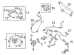
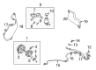
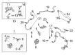
- Q: How to overhaul the power steering pump on Toyota Highlander?A:The power steering pump overhaul process requires starting with removal of the front wheel right side followed by draining power steering fluid after which both the front fender apron seal RH and fan and generator V belt need removal with Special Service Tool 09249-63010. First disconnect the pump from oil reservoir hose No.1 after removing its clip while taking care not to let fluid drip onto the V belt. Then disconnect the pressure feed tube assembly by using a 27mm wrench to hold the pressure port union while removing the bolt and gasket. Begin by detaching the Oil Pressure Switch connector followed by loosening bolt A with Special Service Tool: 09249-63010 and a 14 mm deep socket wrench before removing bolt B. The vane pump assembly requires fixation in a vise using Special Service Tool: 09630-00014 (09631-00132) to proceed with removal of the power steering suction port union and O-ring as well as the flow control valve and its compression spring. Disassemble the vane pump system by first eliminating the oil pressure switch then removing 4 bolts from the vane pump housing rear, and the O-ring before using two screwdrivers to take out a snap ring that will expose the vane pump shaft sub-assembly, rotor, and plates, cam ring, and front side plate with its O-rings. Avoid damaging the housing oil seal during removal before inspecting the vane pump shaft along with its bush in the housing front for proper oil clearance that should not be greater than 0.07 mm (0.0028 in.). Measures of the vane pump plates need to be between 1.405 to 1.411 mm (0.05531 to 0.05555 in.) while the vane pump rotor groove clearance with plates must not exceed 0.03 mm (0.0012 in.). The flow control valve requires inspection for proper operation and leakage while being checked for smooth insertion into its slot with no leakage observed during air application. Measure the free length of the compression spring to ensure it extends at least 30.3 mm (1.193 in.) while checking for damage on the pressure port union. Fasten the new power steering fluid-coated housing oil seal with Special Service Tool: 09950-60010 (09951-00280), 09950-70010 (09951-07100) accompanied by a press tool for correct orientation. Apply power steering fluid onto the housing front bushing surface before you place the w/pulley shaft sub-assembly in while avoiding damage to the oil seal lip. First position the vane pump housing rear with its O-ring before installing the snap ring. The next steps involve putting in vane pump rotor and plates and the camera ring respectively. Finish by putting in the side plate front. The vane pump housing rear should get installed with a new O-ring and proper alignment must be maintained before torquing to 22 Nm (224 kgf-cm, 16 ft-lbf). Smooth rotation of the pump should be checked before you install the power steering oil pressure switch with its new O-ring while torquing it to 21 Nm (214 kgf-cm, 15 ft-lbf). Install the flow control valve as well as its compression spring after which add the pressure port union with a new O-ring and torque it to 69 Nm (704 kgf-cm, 51 ft-lbf) before installing the power steering suction port union with a new O-ring that requires a torque of 12 Nm (122 kgf-cm, 9 ft-lbf). Finally, install the vane pump assembly, torqueing bolt B to 37 Nm (377 kgf-cm, 27 ft-lbf) and bolt A to 26 Nm (264 kgf-cm, 19 ft-lbf) using Special Service Tool: 09249-63010, reconnect the oil pressure switch connector, install the pressure feed tube assembly with a new gasket, torqueing to 52 Nm (525 kgf-cm, 38 ft-lbf), connect the oil reservoir to pump hose No.1, install the fan and generator V belt, the front fender apron seal RH, and the front wheel RH, torqueing to 103 Nm (1,050 kgf-cm, 76 ft-lbf), then bleed the power steering fluid and inspect for leaks.
- Q: How to service and repair the power steering pump on Toyota Highlander?A:The power steering pump servicing process begins with front wheel RH removal and draining power steering fluid followed by taking off both front fender liner RH and front fender apron seal RH. Use Special Service Tool: 09249-63010 to remove the fan and generator V belt followed by disconnecting the oil reservoir to pump hose No.1 through clip removal but keep the V belt free from fluid leakage. Start by disconnecting the pressure feed tube assembly through separating its connector from the Oil Pressure Switch and using a 27 mm spanner for rotating the pressure port union to remove the union bolt and its gasket. The vane pump assembly removal process starts with disconnecting the oil pressure switch followed by loosening bolt A with Special Service Tool: 09249-63010 and a 14 mm deep socket and then removing bolt B together with the vane pump assembly. First remove the suction port union with O-ring from power steering system before removing the pressure port union that contains its O-ring. Detach the flow control valve and compression spring while maintaining safe handling of the oil pressure switch because replacement might be necessary if it shows damage. Extract the w/pulley shaft sub-assembly through removal of the snap ring and shaft while following the step of taking off 4 bolts and an O-ring from the vane pump housing rear. The procedure involves removing the vane plates alongside the vane pump rotor before proceeding to extract the vane pump cam ring and front side plate. During this step the team should detach both the side plate and pump housing front O-rings. Measure the vane pump housing oil seal clearance using a micrometer and caliper gauge after its extraction using a screwdriver with vinyl tape - change the vane pump assembly when clearance exceeds 0.07 mm. Check the vane pump rotor and plates' dimensions and change the assembly if any measurement is lower than minimum standards. Inspect the flow control valve for smooth operation and leakage then install a new spring assembly only if the free length measurement falls below 36.9 mm. The pressure port union also needs inspection for damage with new assembly installation as required. The new oil seal needs to be correctly oriented before the front side plate gets installed with new O-rings while the dents should be correctly aligned. Place the vane pump cam ring with an inscribed mark facing outside before installing the w/pulley shaft sub-assembly and vane pump rotor with outermost inscribed mark while applying power steering fluid on the vane plates. The vane pump housing rear needs a new O-ring during installation while having the straight pin properly aligned before securing it with 4 bolts at 22 Nm torque. Place the vane pump rotation torque gauge to check if it meets the specification of 0.27 Nm or less before installing the power steering oil pressure switch with a new O-ring at 21 Nm torque setting. Begin installation by putting the flow control valve compression spring and the flow control valve together then add the pressure port union with a new O-ring tightened at 69 Nm and after that add the power steering suction port union with a new O-ring tightened at 12 Nm. The final installation involves tightening bolt A briefly followed by tightening bolt B to 43 Nm before applying 30 Nm on bolt A through the use of Special Service Tool: 09249-63010. The pressure feed tube assembly includes a gasket which requires the stopper to touch the pump housing before tightening the union bolt to 51 Nm. Reconnect the oil reservoir to pump hose number one using Special Service Tool: 09249-63010 for installing the fan and generator V belt then reassemble front fender apron seal and front fender liner and front wheel RH at a torque of 103 Nm. The power steering fluid should undergo a bleeding procedure before inspecting for any signs of leakages.


Related Toyota Highlander Parts
 Toyota Highlander Steering Wheel
 Toyota Highlander Power Steering Hose
 Toyota Highlander Drag Link
 Toyota Highlander Power Steering Reservoir
 Toyota Highlander Rack And Pinion
 Toyota Highlander Rack and Pinion Boot
 Toyota Highlander Steering Angle Sensor
 Toyota Highlander Steering Column Cover
 Toyota Highlander Steering Gear Box
 Toyota Highlander Steering Shaft
 Toyota Highlander Tie Rod End
 Toyota Highlander Windshield Wiper Switch