×
ToyotaParts- Hello
- Login or Register
- Quick Links
- Live Chat
- Track Order
- Parts Availability
- RMA
- Help Center
- Contact Us
- Shop for
- Toyota Parts
- Scion Parts
My Garage
My Account
Cart
OEM Toyota Avalon Rack And Pinion
Steering Gear- Select Vehicle by Model
- Select Vehicle by VIN
Select Vehicle by Model
orMake
Model
Year
Select Vehicle by VIN
For the most accurate results, select vehicle by your VIN (Vehicle Identification Number).
15 Rack And Pinions found


Toyota Avalon Steering Gear Part Number: 45510-07010
$568.96 MSRP: $833.82You Save: $264.86 (32%)Ships in 1-3 Business Days
Toyota Avalon Rack Sub-Assembly, Power Steering, Front Part Number: 44204-33070
$413.92 MSRP: $606.61You Save: $192.69 (32%)Ships in 1-3 Business Days
Toyota Avalon Rack, Front Part Number: 44204-07010
$401.78 MSRP: $588.81You Save: $187.03 (32%)Ships in 1-3 Business Days
Toyota Avalon Steering Gear Part Number: 44250-07011
$619.05 MSRP: $907.22You Save: $288.17 (32%)
Toyota Avalon Gear Assembly Part Number: 44250-07190
$679.29 MSRP: $995.50You Save: $316.21 (32%)Ships in 1-3 Business DaysToyota Avalon Steering Gear Part Number: 44250-07181
$699.72 MSRP: $1025.44You Save: $325.72 (32%)Toyota Avalon Steering Gear Part Number: 44250-07151
$720.26 MSRP: $1055.55You Save: $335.29 (32%)Ships in 1-2 Business DaysToyota Avalon Steering Gear Part Number: 44250-07161
$729.11 MSRP: $1068.52You Save: $339.41 (32%)Ships in 1-3 Business DaysToyota Avalon Steering Gear Part Number: 44250-07162
$900.50 MSRP: $1319.69You Save: $419.19 (32%)Ships in 1-3 Business Days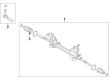
Toyota Avalon Steering Gear Part Number: 44250-07182
$909.24 MSRP: $1332.50You Save: $423.26 (32%)Ships in 1-3 Business DaysToyota Avalon Steering Gear Part Number: 44250-07152
$936.59 MSRP: $1372.58You Save: $435.99 (32%)Ships in 1-3 Business DaysToyota Avalon Rack Part Number: 44204-33031
$325.30 MSRP: $464.46You Save: $139.16 (30%)Ships in 1-3 Business Days
Toyota Avalon GEAR ASSY, POWER STE Part Number: 44250-07102
$675.42 MSRP: $989.83You Save: $314.41 (32%)Ships in 1-2 Business DaysToyota Avalon Rack, Front Part Number: 44204-07011

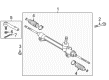
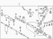
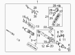
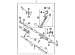
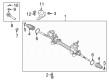
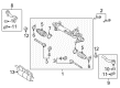
Toyota Avalon Rack And Pinion
Choose genuine Rack And Pinion that pass strict quality control tests. You can trust the top quality and lasting durability. Shopping for OEM Rack And Pinion for your Toyota Avalon? Our website is your one-stop destination. We stock an extensive selection of genuine Toyota Avalon parts. The price is affordable so you can save more. It only takes minutes to browse and find the exact fit. Easily add to cart and check out fast. Our hassle-free return policy will keep you stress-free. We process orders quickly for swift delivery. Your parts will arrive faster, so you can get back on the road sooner.
Our Toyota Avalon Rack And Pinion can be simply described as a device that relays turning input from the steering wheel into lateral output in the front wheels. This radial-flow rack and pinion its made up of helical gears enveloped in a metal casing; the rack is linked to tie rods for wheel steering. Nearly all Avalon cars have power-assisted rack and pinion steering with vectored hydraulic power supplied by the pressure of the fluid of a rotary valve on the pinion gear. Some of the typical problems that can accompany it are leaking of seals or hoses, a worn gear or inner tie-rod joint. Proper maintenance has to be conducted so as not to cause harm and have a good and a considerable steering rotation.
Toyota Avalon Rack And Pinion Parts and Q&A
- Q: How to remove the rack and pinion power steering gear on Toyota Avalon?A:The first step to remove a rack and pinion power steering rack and pinion involves coating specific components using power steering fluid and MP grease or silicon grease or molybdenum disulfide lithium base grease. Position the front wheels in a straight ahead direction before you detach the front wheels together with the left and right front fender apron seals. Start by fixing the Steering Wheel with a seat belt to stop rotation before marking the positions of the steering intermediate shaft assembly and the power steering rack and pinion assembly before you separate them. The left tie rod assembly needs both the castle nut and cotter pin removal followed by detachment from the left steering knuckle with Special Service Tool: 09628-62011. The same process should be done to disassemble the right tie rod assembly. First separate both front stabilizer link assemblies before disconnecting the stabilizer bar bush No.1 on the left side by removing its two bolts. Then finish by removing the same components on the right side. Use Special Service Tool: 09023-12701 to disconnect pressure feed tube assembly from power steering rack and pinion as well as the return tube assembly. Then remove the two bolts to undo the pressure feed tube clamp from the power steering rack and pinion assembly. Finish the power steering rack and pinion assembly detachment by removing all two bolts and nuts while maintaining your hands from turning the nut because it possesses its own built-in protection and gently loosen the bolt which has the nut in place.
- Q: How to service and repair the Rack And Pinion on Toyota Avalon?A:Service and repair operations for the rack and pinion begin by using Special Service Tool: 09612-00012 to fixate the Rack And Pinion assembly in a vise before removing the pressure tubes with Special Service Tool: 09023-38200 followed by extracting the 4 O-rings. Perform markings on the tie rod and rack ends separately before starting to loosen the lock nuts so you can remove both RH and LH tie rod components and locks. Then repeat this procedure for the other side. Using a screwdriver to loosen the clamp allows the removal of RH and LH clips rack boots and clamps while safeguarding the rack boot and marking the RH and LH rack boot. Unstake the claw washer with a screwdriver and hammer while using a 24 mm spanner to hold the rack and pinion then extract the rack end by following Special Service Tool: 09922-10010 in the right direction. Use Special Service Tool 09922-10010 to remove the rack guide spring cap lock nut before extracting the rack guide spring and rack guide sub-assembly through the special tool 09631-10021. Start by using Special Service Tool: 09616-00011 to stop control valve shaft rotation during removal of the self-locking nut before you proceed to take out the dust seal and control valve housing with control valve assembly while marking alignment matchmarks. To protect the oil seal lip, apply vinyl tape on the control valve shaft serrations before extracting the control valve assembly with its oil seal. Then remove the oil seal from the assembly. To remove the rack and pinion assembly begin by detaching the rack housing No. 2 bracket and grommet then steer the cylinder end stopper clockwise with Special Service Tool: 09631-10021 until the wire end becomes visible before turning it counter clockwise. Press out the rack and pinion with a brass bar and hammer to remove the bushing along with the O-ring while using Special Service Tool: 09950-60010 (09951-00290), 09950-70010 (09951-07360). The technician should inspect rack and pinion runout and wear before replacing the oil seal and bearing by using Special Service Tool: 09950-60010 (09951-00250), 09950-70010 (09951-07200). New oil seals need power steering fluid coating on the lip before insertion with Special Service Tool: 09950-60010 (09951-00180, 09951-00320, 09952-06010), 09950-70010 (09951-07200). To replace the two bearings start by removing them through tapping and then pressing new ones that should receive molybdenum disulfide lithium base grease coating. Replace the oil seal from the bushing with Special Service Tool: 09527-20011, 09612-24014 (09613-22011) while installing new teflon rings and O-rings with caution to the grooves. The assembly process starts with applying fluid or grease onto the components followed by using Special Service Tool: 09950-60010 (09951-00240, 09951-00430, 09952-06010), 09950-70010 (09951-07360) to insert the rack and pinion into its housing while protecting the oil seal lip. The bushing installation requires a new O-ring in the right position before inserting the cylinder end stopper with wire alignment. Test the rack housing air tightness using Special Service Tool: 09631-12071 by applying 53 kPa (400 mm Hg, 15.75 inch Hg) vacuum pressure for 30 seconds. Reposition the rack housing No. 2 bracket along with its grommet prior to mounting the control valve assembly with special attention to applying power steering fluid onto teflon rings. After assembly of the oil seal and control valve housing the mechanic should install new bolts with 18 Nm (180 kgf-cm, 13 ft. lbs.) torque and apply the self-locking nut using 25 Nm (250 kgf-cm, 18 ft. lbs.) torque. Install the rack housing cap with dust seal after coating it with sealant then torque to 59 Nm (600 kgf-cm, 43 ft. lbs.) while staking the cap. The rack guide sub-assembly should be installed with its spring and cap while using Special Service Tool: 09631-10021 to adjust preload from 0.8 - 1.4 Nm (8 - 14 kgf-cm, 6.9 - 12.2 inch lbs.) or 0.8 - 1.4 inch lbs. Before mounting the RH and LH claw washers and rack ends, apply sealant to the rack guide spring cap lock assembly then torque it to 50 Nm (510 kgf-cm, 37 ft. lbs.) before revising the total preload before proceeding.


Related Toyota Avalon Parts
 Toyota Avalon Power Steering Pump
 Toyota Avalon Steering Wheel
 Toyota Avalon Drag Link
 Toyota Avalon Power Steering Control Valve
 Toyota Avalon Power Steering Reservoir
 Toyota Avalon Rack and Pinion Boot
 Toyota Avalon Steering Angle Sensor
 Toyota Avalon Steering Column
 Toyota Avalon Steering Column Cover
 Toyota Avalon Steering Shaft
 Toyota Avalon Tie Rod End
 Toyota Avalon Universal Joint