×
ToyotaParts- Hello
- Login or Register
- Quick Links
- Live Chat
- Track Order
- Parts Availability
- RMA
- Help Center
- Contact Us
- Shop for
- Toyota Parts
- Scion Parts
My Garage
My Account
Cart
OEM 2003 Toyota Avalon Rack And Pinion
Steering Rack And Pinion- Select Vehicle by Model
- Select Vehicle by VIN
Select Vehicle by Model
orMake
Model
Year
Select Vehicle by VIN
For the most accurate results, select vehicle by your VIN (Vehicle Identification Number).
2 Rack And Pinions found

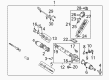
2003 Toyota Avalon Rack, Front
Part Number: 44204-07010$401.78 MSRP: $588.81You Save: $187.03 (32%)Ships in 1-3 Business DaysProduct Specifications- Other Name: Rack Sub-Assembly, Power; Rack And Pinion Rack Gear, Front; Steering Gearbox; Steering Rack; Rack Sub-Assembly, Power Steering
- Position: Front
- Part Name Code: 44204
- Item Weight: 5.50 Pounds
- Item Dimensions: 33.3 x 3.2 x 2.8 inches
- Condition: New
- Fitment Type: Direct Replacement
- SKU: 44204-07010
- Warranty: This genuine part is guaranteed by Toyota's factory warranty.
 Product Specifications
- Other Name: Gear Assembly, Power Steering; Steering Gearbox
- Replaces: 44250-07061, 44250-07040, 44250-06120
- Part Name Code: 44250
- Item Weight: 21.40 Pounds
- Item Dimensions: 59.9 x 12.1 x 7.2 inches
- Condition: New
- Fitment Type: Direct Replacement
- SKU: 44250-07062
- Warranty: This genuine part is guaranteed by Toyota's factory warranty.
2003 Toyota Avalon Rack And Pinion
Looking for affordable OEM 2003 Toyota Avalon Rack And Pinion? Explore our comprehensive catalogue of genuine 2003 Toyota Avalon Rack And Pinion. All our parts are covered by the manufacturer's warranty. Plus, our straightforward return policy and speedy delivery service ensure an unparalleled shopping experience. We look forward to your visit!
2003 Toyota Avalon Rack And Pinion Parts Q&A
- Q: How to remove and install the Rack And Pinion on 2003 Toyota Avalon?A: The first step in rack and pinion removal requires front wheel alignment to a straight position followed by removing the steering wheel pad and steering wheel. Tear down the RH and LH tie rod ends together with the intermediate shaft sub-assembly and clamp plate through the removal of their nut and clamp plate. Special Service Tool 09023-38400 will help with disconnecting pressure feed and return tubes from which technicians should extract 2 O-rings. Proceed to disconnect the stabilizer bar while you remove only the four connecting bolts. Start by untightening the No. 1 fuel tube protector through removing its 2 bolts and nut. Next, install the Rack And Pinion assembly by unfastening the 2 set bolts and nuts followed by a possible stabilizer bar lift to prevent damaging the turning pressure tubes. Install the Rack And Pinion assembly from the LH vehicle side by using 2 Rack And Pinion assembly set bolts with nuts and torquing them to 181 Nm (1,850 kgf-cm, 134 ft. lbs.). The No. 1 fuel tube protector gets secured with 2 bolts and nut before attaching the stabilizer bar through 4 bolts with torques set at 19 Nm (190 kgf-cm, 14 ft. lbs.). The installation requires power steering fluid to coat 2 new O-rings which will be inserted to pressure feed and return tubes before using Special Service Tool: 09023-38400 to validate the proper alignment between the tool and torque wrench for accurate torques of 28 Nm (290 kgf-cm, 21 ft. lbs.). Begin with clamping the plate with a nut while tightening it to 10 Nm (100 kgf-cm, 7 ft. lbs.) then progress to connecting the intermediate shaft sub-assembly and the RH and LH tie rod ends. Straighten the front wheels before you position the spiral cable in the center point. Afterwards, install the steering wheel by matching the matchmarks then tighten the set nut temporarily before you join the connector. The power steering system requires bleeding before continuing to the steering wheel center point check and the eventual torque of the steering wheel set nut to 50 Nm (510 kgf-cm, 37 ft. lbs.). Complete the installation by attaching the steering wheel pad then examine the front wheel alignment followed by VSC steering angle sensor zero point calibration when this feature is present.
Related 2003 Toyota Avalon Parts
 2003 Toyota Avalon Power Steering Hose
 2003 Toyota Avalon Power Steering Pump
 2003 Toyota Avalon Steering Wheel
 2003 Toyota Avalon Drag Link
 2003 Toyota Avalon Power Steering Control Valve
 2003 Toyota Avalon Power Steering Reservoir
 2003 Toyota Avalon Rack and Pinion Boot
 2003 Toyota Avalon Steering Angle Sensor
 2003 Toyota Avalon Steering Column Cover
 2003 Toyota Avalon Steering Gear Box
 2003 Toyota Avalon Steering Shaft
 2003 Toyota Avalon Tie Rod End