×
ToyotaParts- Hello
- Login or Register
- Quick Links
- Live Chat
- Track Order
- Parts Availability
- RMA
- Help Center
- Contact Us
- Shop for
- Toyota Parts
- Scion Parts
My Garage
My Account
Cart
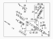
OEM 2004 Toyota Avalon Rack And Pinion
Steering Rack And Pinion- Select Vehicle by Model
- Select Vehicle by VIN
Select Vehicle by Model
orMake
Model
Year
Select Vehicle by VIN
For the most accurate results, select vehicle by your VIN (Vehicle Identification Number).
3 Rack And Pinions found

2004 Toyota Avalon Rack, Front
Part Number: 44204-07010$401.78 MSRP: $588.81You Save: $187.03 (32%)Ships in 1-3 Business DaysProduct Specifications- Other Name: Rack Sub-Assembly, Power; Rack And Pinion Rack Gear, Front; Steering Gearbox; Steering Rack; Rack Sub-Assembly, Power Steering
- Position: Front
- Part Name Code: 44204
- Item Weight: 5.50 Pounds
- Item Dimensions: 33.3 x 3.2 x 2.8 inches
- Condition: New
- Fitment Type: Direct Replacement
- SKU: 44204-07010
- Warranty: This genuine part is guaranteed by Toyota's factory warranty.
- Product Specifications
- Other Name: Rack Sub-Assembly, Power; Rack And Pinion Rack Gear, Front; Steering Gearbox; Steering Rack; Rack Sub-Assembly, Power Steering
- Position: Front
- Part Name Code: 44204
- Item Weight: 5.70 Pounds
- Item Dimensions: 33.6 x 3.2 x 2.8 inches
- Condition: New
- Fitment Type: Direct Replacement
- SKU: 44204-07011
- Warranty: This genuine part is guaranteed by Toyota's factory warranty.
 Product Specifications
- Other Name: Gear Assembly, Power Steering; Steering Gearbox
- Replaces: 44250-07061, 44250-07040, 44250-06120
- Part Name Code: 44250
- Item Weight: 21.40 Pounds
- Item Dimensions: 59.9 x 12.1 x 7.2 inches
- Condition: New
- Fitment Type: Direct Replacement
- SKU: 44250-07062
- Warranty: This genuine part is guaranteed by Toyota's factory warranty.
2004 Toyota Avalon Rack And Pinion
Looking for affordable OEM 2004 Toyota Avalon Rack And Pinion? Explore our comprehensive catalogue of genuine 2004 Toyota Avalon Rack And Pinion. All our parts are covered by the manufacturer's warranty. Plus, our straightforward return policy and speedy delivery service ensure an unparalleled shopping experience. We look forward to your visit!
2004 Toyota Avalon Rack And Pinion Parts Q&A
- Q: How to disassemble and reassemble the Rack And Pinion on 2004 Toyota Avalon?A: The Rack And Pinion assembly needs to be fixed in a vise using SST 09612-00012 while removing the 2 turn pressure tubes with SST 09023-38200 and taking out the 4 O-rings. Sign the tie rod ends and rack ends before unlocking their lock nuts to detach the hardware. A screwdriver should be used to loosen the clamps before taking out the clips and rack boots while preserving the rack boots from damage. First hammer and screwdriver unstake the claw washers to then detach the rack ends using SST 09922-10010 while securing the rack and pinion with a 24 mm spanner. Apply SST 09922-10010 to remove both the rack guide spring cap lock nut followed by the rack guide spring cap from the system. After removing the self-locking nut using SST 09616-00011 and the rack housing cap you can progress to separate the dust seal alongside control valve housing with included control valve assembly. Always make matchmarks before proceeding. The control valve shaft must receive wind vinyl tape to protect the oil seal lips before pressing the control valve assembly out for oil seal removal. Use SST 09631-10021 to rotate the cylinder end stopper clockwise and counterclockwise before removing it by uncoupling the rack housing No. 2 bracket and grommet. Press out the oil seal of the rack and pinion by using SST (09950-60010, 09951-00290 and 09950-70010, 09951-07360). To repair the rack and pinion SST 09950-60010 (09951-00250) and SST 09950-70010 (09951-07200) must replace the oil seal and bearing and power steering fluid must coat new oil seal lips. Install bearing replacements by coating them with grease before pressing them inside using SST 09950-60010 (09951-00250, 09951-00310, 09952-06010) and SST 09950-70010 (09951-07200). Lake SST 09527-20011, 09612-24014 (09613-22011) to replace the bushing oil seals before installing fresh Teflon rings and O-rings without damaging the grooves. Reassemble the rack and pinion by applying power steering fluid or grease on the parts and then pressing in the oil seal with SST 09950-60010 (09951-00240, 09951-00430, 09952-06010) before carefully placing the rack and pinion into the rack housing keeping the oil seal lip protected. Fit the bushing while using a new O-ring properly oriented followed by installing the cylinder end stopper with its new wire. Use SST 09631-12071 vacuum equipment to conduct the air tightness test by creating vacuum pressure and watching for pressure changes. Install the rack housing No. 2 grommet and bracket by aligning the matchmarks after which install the control valve assembly while taking care to shield both the oil seal and Teflon rings. SST 09612-22011 oil seal goes in first then install the control valve housing and its new gasket using the specified bolt torques. Begin by applying sealant to the rack housing cap which needs to be installed with the rack housing cap and dust seal and followed by SST 09616-00011 self-locking nut. The rack guide sub-assembly alongside its spring and cap components need to be installed while SST 09631-10021 adjusts total preload to reach the specified torque setting. Apply sealant to the rack guide spring cap lock nut before measuring total preload a second time and putting on the claw washers and rack ends while maintaining proper alignment during torqueing steps. The installation procedure requires you to install rack boots, clamps, and clips without clogging before installing tie rod ends with specified torque settings followed by new O-ring installation before torquing the 2 turn pressure tubes.
Related 2004 Toyota Avalon Parts
 2004 Toyota Avalon Power Steering Hose
 2004 Toyota Avalon Power Steering Pump
 2004 Toyota Avalon Steering Wheel
 2004 Toyota Avalon Drag Link
 2004 Toyota Avalon Power Steering Control Valve
 2004 Toyota Avalon Power Steering Reservoir
 2004 Toyota Avalon Rack and Pinion Boot
 2004 Toyota Avalon Steering Angle Sensor
 2004 Toyota Avalon Steering Column Cover
 2004 Toyota Avalon Steering Gear Box
 2004 Toyota Avalon Steering Shaft
 2004 Toyota Avalon Tie Rod End