- Hello
- Login or Register
- Quick Links
- Live Chat
- Track Order
- Parts Availability
- RMA
- Help Center
- Contact Us
- Shop for
- Toyota Parts
- Scion Parts

Popular OEM Toyota Avalon Parts
- Body & Hardware Parts View More >
- Electrical Parts View More >
- Engine Parts View More >
- Air & Fuel Delivery Parts View More >
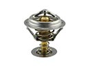
- Belts & Cooling Parts View More >
- Steering Parts View More >
- Suspension Parts View More >
- Emission Control & Exhaust Parts View More >
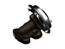
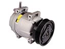
- A/C & Heating Parts View More >
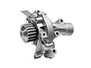
- Charging & Starting Parts View More >
- Brakes Parts View More >
- Transmission Parts View More >


Why Buy Genuine Toyota Avalon Parts From ToyotaPartsNow.com
ToyotaPartsNow.com highlights the reliability of OEM Toyota Avalon parts right at your fingertips. Our skilled staff assists customers in selecting the right Toyota Avalon parts and provides expert help with any unique part requests. At ToyotaPartsNow.com, we make all Toyota Avalon parts available to you quickly and efficiently through our fast order and reliable ship process. Our service is designed to make finding the correct Toyota Avalon parts fast and easy whether you are an amateur or a professional. We offer access to a broad inventory that includes a wide range of Toyota years and variants. Affordable prices, quick processing and professional service are also our specialty to ensure your car remains in top condition with OEM Toyota Avalon parts. You can feel confident shopping with us because all Toyota Avalon parts, such as Headlights & Lighting you purchase from our store are of genuine quality and built to last.
For two decades starting from 1994 Toyota released six different iterations of its Avalon sedan to show its dedication to engineering achievement. The 1994 model year Avalon operated on a 3.0L V6 1MZ-FE engine and 4-speed A340E automatic transmission for 192 horsepower with 210 lb-ft of torque. In 2005 Toyota released the second-generation Avalon model with its 2GR-FE V6 3.5L engine that produced 268 horsepower along with 248 lb-ft of torque while using a standard 6-speed automatic transmission. Toyota continues to advance engine performance through its dedication to provide vehicles with both improved handling and enhanced fuel efficiency benefits. The front-wheel drive standard equipment of the Avalon helps improve both vehicle traction and stability particularly during difficult weather situations. Standard safety features in a fifth-generation Avalon include blind-spot monitoring and adaptive cruise control and it comes with XLE, Limited, XSE, Touring trim levels. Customers who choose the vehicle can select premium interior selections while also choosing from 17-inch alloy wheel options. Avalon vehicles absolutely require genuine Toyota parts because Toyota has rigorous quality control measures to ensure outstanding performance and safety protection in addition to their functional excellence. The benefits of performance excellence from OEM Toyota Avalon components stem from their reliability with precise fitment abilities together with operational effectiveness for vehicle owners. The quality commitment shown by Toyota for dependable driving extends from start to finish of the Avalon model period.
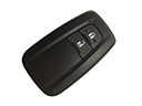
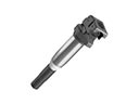
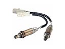
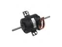
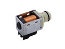
Known for its convenience and reliability, the Toyota Avalon can still have some electrical and engine problems. Among common failures that may be caused by a bad Toyota Avalon ignition coil is engine misfiring and the triggering of the Check Engine Light. High-mileage Avalon's often report this issue with the part. To fix this problem, you need to replace the ignition coil on all affected Toyota Avalon models. The last electrical issue is a faulty back window sunshade motor. It may grind and refuse to retract as expected. A short-term fix involves removing the Toyota Avalon motor along with the fuse. But it will require replacing the Toyota Avalon window sunshade assembly to make a long-lasting repair. Also, a faulty oxygen sensor can trigger the Check Engine Light. This situation should be addressed by replacing the defective sensor to keep the engine running well and the car reliable. Sometimes these issues may not be picked up on until symptoms like rough idling, stalling or poor fuel economy develop and Toyota Avalon's regular maintenance is important.
Toyota Avalon Parts and Q&A
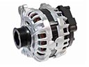
- Q: How to service and repair the alternator on Toyota Avalon?A:To service/ repair the alternator, dismantle it which involves removing the rear end cover, brush holder, and voltage regulator. Disassemble the rectifier holder, the pulley and remove the rectifier end frame. To assemble, attach a rotor, rectifier end frame, and use the right tools and right torque values to assemble.
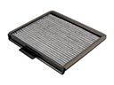
- Q: How to replace the Cabin Air Filter on Toyota Avalon?A:In order to replace the air refiner filter, begin by removing the glove compartment pieces. Next, remove the filter cover, and remove the old filter and unscrew it out of the frame. Install the new filter into the frame, reconnect the cover and reinsert the glove compartment parts.
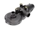
- Q: How to reassemble the radiator on Toyota Avalon?A:To put the radiator back together, clean the point where the O-rings are in contact, put in new O-rings and attach the oil cooler. Fixed cooler pipe, do not place anything in the lock plate groove. Prepare Special Service Tools, caulk the lock plate and inspect water leaks.


