×
ToyotaParts- Hello
- Login or Register
- Quick Links
- Live Chat
- Track Order
- Parts Availability
- RMA
- Help Center
- Contact Us
- Shop for
- Toyota Parts
- Scion Parts
My Garage
My Account
Cart
OEM Toyota Avalon Wheel Bearing
Hub Bearing- Select Vehicle by Model
- Select Vehicle by VIN
Select Vehicle by Model
orMake
Model
Year
Select Vehicle by VIN
For the most accurate results, select vehicle by your VIN (Vehicle Identification Number).
16 Wheel Bearings found


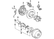
Toyota Avalon Hub & Bearing Assembly, Rear Axle, Passenger Side Part Number: 42450-06090
$341.85 MSRP: $500.99You Save: $159.14 (32%)Ships in 1-3 Business Days

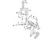
Toyota Avalon Hub Assembly, Front Part Number: 43502-0E030
$130.65 MSRP: $184.95You Save: $54.30 (30%)


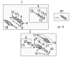
Toyota Avalon Wheel Bearing Part Number: 90080-36193
$102.37 MSRP: $143.70You Save: $41.33 (29%)Ships in 1-3 Business Days

Toyota Avalon Hub & Bearing Assembly, Rear Axle, Passenger Side Part Number: 42450-06110
$344.80 MSRP: $505.32You Save: $160.52 (32%)Ships in 1 Business Day
Toyota Avalon Hub & Bearing, Driver Side Part Number: 42460-06070
$344.80 MSRP: $505.32You Save: $160.52 (32%)Ships in 1-3 Business Days

Toyota Avalon Hub & Bearing Assembly, Rear Axle, Driver Side Part Number: 42460-48011
$478.62 MSRP: $701.43You Save: $222.81 (32%)Ships in 1-2 Business Days


Toyota Avalon Bearing, Passenger Side Part Number: 90363-A0004
$35.48 MSRP: $49.39You Save: $13.91 (29%)Ships in 1-3 Business Days

Toyota Avalon Hub & Bearing Assembly, Rear Axle, Passenger Side Part Number: 42450-33020
$413.81 MSRP: $606.44You Save: $192.63 (32%)Ships in 1-3 Business Days


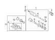
Toyota Avalon Bearing (For Front Drive Shaft) Part Number: 90080-36133
$32.13 MSRP: $44.73You Save: $12.60 (29%)Ships in 1-2 Business Days

Toyota Avalon Wheel Bearings Part Number: 90369-43008
$102.49 MSRP: $143.86You Save: $41.37 (29%)Ships in 1-3 Business Days
Toyota Avalon Hub Assembly, Rear Part Number: 42410-0R030
$255.71 MSRP: $365.09You Save: $109.38 (30%)Ships in 1-3 Business Days
Toyota Avalon Hub Assembly Part Number: 42410-33040
$428.45 MSRP: $627.90You Save: $199.45 (32%)Ships in 1-3 Business DaysToyota Avalon Hub Assembly, Passenger Side Part Number: 42450-48011
$515.62 MSRP: $755.65You Save: $240.03 (32%)Ships in 1 Business Day

Toyota Avalon Hub Sub-Assembly, Front Axle, Passenger Side Part Number: 43502-06040
$162.49 MSRP: $230.03You Save: $67.54 (30%)


Toyota Avalon Hub Assembly, Front Part Number: 43550-06010
$268.17 MSRP: $382.89You Save: $114.72 (30%)

Toyota Avalon Hub Assembly, Front Part Number: 43550-06050
$278.66 MSRP: $397.86You Save: $119.20 (30%)
Toyota Avalon Wheel Bearing
Choose genuine Wheel Bearing that pass strict quality control tests. You can trust the top quality and lasting durability. Shopping for OEM Wheel Bearing for your Toyota Avalon? Our website is your one-stop destination. We stock an extensive selection of genuine Toyota Avalon parts. The price is affordable so you can save more. It only takes minutes to browse and find the exact fit. Easily add to cart and check out fast. Our hassle-free return policy will keep you stress-free. We process orders quickly for swift delivery. Your parts will arrive faster, so you can get back on the road sooner.
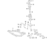
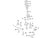
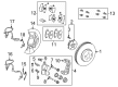
This automobile spare part is called the Wheel Bearing; it plays a very vital role in improving the durability and efficiency of the Toyota Avalon which is a full-size sedan automobile that is widely known for its quality and safety features. This Wheel Bearing plays a role of enabling the wheels to turn smoothly and freely with little resistance and therefore enabling the wheel and the tire to work optimally. For the years now, different Avalon models have incorporated innovative features of the hub and bearing systems, mostly the integral hub and bearing assembly and in some cases the ABS sensor. Maintenance of the Wheel Bearing is very important since its failure leads to auditory emissions and vibrations, as well as potential wheel detachment. Another aspect that has always had praises showered on the Toyota Avalon is safety and specifically, safety features; it has been named a Top Safety Pick by the IIHS, the integrity of the Wheel Bearing needs to be maintained. Operating across Avalon generations ranging from the current hybrid models and the previous generations, the Wheel Bearing can be said to be a standout product in the market because of the strength and reliability with which it is constructed. Other features include the replaceable tapered roller bearings and ease in Inspection and maintenance which all add up to the efficiency as well as safety of the vehicle. All in all, the Wheel Bearing plays a significant role in the working and protection of the Toyota Avalon vehicle hence contributing significantly to the Toyota Avalon engineering.
Toyota Avalon Wheel Bearing Parts and Q&A
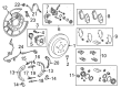
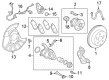
- Q: How to remove the rear axle hub and Wheel Bearing assembly on the LH side on Toyota Avalon?A:The first step for removing the LH side rear axle hub and bearing assembly starts with the removal of the rear wheel. The rear disc Brake Caliper assembly LH requires a bolt removal followed by flexible hose detachment from the Shock Absorber before removing the 2 bolts to remove the caliper assembly. A wire should be used along with an equivalent device to hold the brake caliper in position while the flexible hose remains unsupported. The skid control sensor requires unplugging its connector after removing the rear disc and disconnecting the sensor. Detachment of the hub and bearing assembly LH occurs by removing its four bolts.
- Q: How to install the rear axle hub and Wheel Bearing assembly LH on Toyota Avalon?A:The installation process of rear axle hub and bearing assembly LH starts with 4 bolt tightening to 80 Nm (816 kgf-cm, 59 ft-lbf). The skid control sensor connector needs to be connected properly and the sensor wire should remain untwisted during this process. Check the rear axle hub bearing for looseness alongside measuring the rear axle hub runout. Install the rear disc first then attach the rear disc Brake Caliper assembly LH while torquing its 2 bolts to 62 Nm (632 kgf-cm, 46 ft-lbf) yet maintain avoidance of brake hose twisting. Insert the rear flexible hose first after screwing its bolt to 19 Nm (192 kgf-cm, 14 ft-lbf). Secure the rear wheel afterward by torquing it to 103 Nm (1.050 kgf-cm, 76 ft-lbf). Install the ABS speed sensor signal according to system specifications which include EBD with TRAC and VSC or EBD requirements alone.


Related Toyota Avalon Parts
 Toyota Avalon Brake Pads
 Toyota Avalon Brake Caliper
 Toyota Avalon Speed Sensor
 Toyota Avalon Backing Plate
 Toyota Avalon Brake Caliper Bracket
 Toyota Avalon Brake Fluid Pump
 Toyota Avalon Brake Line
 Toyota Avalon Hydraulic Hose
 Toyota Avalon Wheel Cylinder Repair Kit
 Toyota Avalon Wheel Hub
 Toyota Avalon Wheel Stud
 Toyota Avalon Yaw Sensor