×
ToyotaParts- Hello
- Login or Register
- Quick Links
- Live Chat
- Track Order
- Parts Availability
- RMA
- Help Center
- Contact Us
- Shop for
- Toyota Parts
- Scion Parts
My Garage
My Account
Cart
OEM Toyota Avalon Power Steering Pump
Power Steering Pump Unit- Select Vehicle by Model
- Select Vehicle by VIN
Select Vehicle by Model
orMake
Model
Year
Select Vehicle by VIN
For the most accurate results, select vehicle by your VIN (Vehicle Identification Number).
2 Power Steering Pumps found


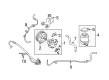
Toyota Avalon Power Steering Pump Part Number: 44310-07040
$317.57 MSRP: $453.41You Save: $135.84 (30%)Ships in 1-2 Business Days

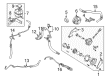
Toyota Avalon Pump Assembly, Vane Part Number: 44320-07012
$299.96 MSRP: $428.28You Save: $128.32 (30%)
Toyota Avalon Power Steering Pump
Choose genuine Power Steering Pump that pass strict quality control tests. You can trust the top quality and lasting durability. Shopping for OEM Power Steering Pump for your Toyota Avalon? Our website is your one-stop destination. We stock an extensive selection of genuine Toyota Avalon parts. The price is affordable so you can save more. It only takes minutes to browse and find the exact fit. Easily add to cart and check out fast. Our hassle-free return policy will keep you stress-free. We process orders quickly for swift delivery. Your parts will arrive faster, so you can get back on the road sooner.
The Power Steering Pump of Toyota Avalon vehicles is a working component that creates hydraulic pressure and force needed to ease steering. With the help of hydraulic power, the pump removes the extra load of turning the steering wheel and makes it much easier for the drivers to manage their vehicles on the road. Toyota Avalon Power Steering Pump employs hydraulic actuators to boost the steering force; there is a linkage between the wheels and the steering wheel in case of the electrical system power outage. Different types of power steering systems are hydraulic, electric, and electronic and the Toyota Avalon automobiles enables the driver to exert little effort while steering particularly at slow rates and at standstill.
Toyota Avalon Power Steering Pump Parts and Q&A
- Q: How to remove the Power Steering Pump on Toyota Avalon?A:The first step in power steering vane pump removal requires you to avoid excessive tightening force on the vise while you should add power steering fluid to designated parts of the assembly along with precautions for V belt contamination prevention. Start the procedure by taking off the front wheel from the right-hand side and draining all power steering fluid. The first step entails taking out both the front fender apron seal on the right side along with the fan and generator V belt. The first step is to remove the clip from the oil reservoir to pump hose No.1 followed by disconnecting the pressure feed tube assembly through union bolt removal and separating the assembly clamp before removing its gasket. The vane pump assembly requires removal after disconnecting the connector at the power steering oil pressure switch and unfastening the two attachment bolts.
- Q: How to service and repair the Power Steering Pump on Toyota Avalon?A:Industry experts start by effortlessly dismantling the Power Steering Pump with attention to avoiding excessive vise pressure during the process. The first step requires measuring the PS vane pump rotating torque at 0.3 Nm (2.8 kgf-cm, 2.4 inch lbs.) or below while inspecting for normal rotation and absence of abnormal noises. Utilizing Special Service Tool: 09960-10010 (09962-01000, 09963-01000) stop the pulley from turning and detach its nut before removing the vane pump shaft unit of pulley. Start by removing the vane pump suction and pressure port unions together with their O-rings and subsequently the front and rear brackets by disassembling 3 bolts and 2 nuts. The maintenance steps include unbolting and removing the pressure port union followed by extracting the flow control valve together with its spring and its specified O-rings. To remove all components from the rear housing one must first remove four housing bolts and two O-rings before extracting the wave washer alongside the side plate, gasket, cam ring and ten vane plates and the vane pump rotor with careful attention to prevent dropped parts. Remove the front housing vane pump shaft together with its accompanying 2 straight pins. To check the vane pump condition measure the shaft clearance with the bushing since it should remain within 0.03 to 0.05 mm (0.0012 to 0.0020 inch). Keep in mind the maximum acceptable value is 0.07 mm (0.0028 inch). If necessary you must replace both the front housing and vane pump shaft. The inspection of vane pump components requires verification of the height at 8.6 mm (0.339 inch) while measuring thickness at 1.397 mm (0.0550 inch) and verifying length at 14.991 mm (0.5902 inch). Verify that no space exceeds 0.035 mm (0.0014 inch) exists between vane plate and vane pump rotor groove. A proper flow control valve test requires power steering fluid application and a smooth entry into the hole while compressed air should produce a pressure of 392 - 490 kPa at 4 - 5 kgf/cm2 or 57 - 71 psi to verify no leakage occurs. Check the free length of the spring. Replace it if the measurement falls below 32.3 mm (1.272 inch). Special Service Tool 09950-60010 (09951-00330) and 09950-70010 (09951-07100) can be used to correctly install a new oil seal by pressing it into place after careful removal using a vinyl tape-wrapped screwdriver and subsequent application of power steering fluid to the seal lip. After coating the specified components with power steering fluid technicians should insert two fresh straight pins using a plastic hammer followed by installing the vane pump shaft. Place the cam ring holes directly onto the straight pins then install it with its inscribed mark visible to the outside while adding the vane pump rotor and a new snap ring. Guided by proper orientation, fit the 10 vane plates outward with round ends while adding a new gasket followed by the side plate until the straight pins show alignment. Secure the 4 bolts that fasten the rear housing with power steering fluid-coated O-rings tight at 17 Nm (170 kgf-cm, 12 ft. lbs.). Fitting the spring first requires correct direction placement of the flow control valve and pressure port union before tightening the hardware to 83 Nm (850 kgf-cm, 62 ft. lbs) using a new O-ring coated with power steering fluid. The suction port union gets installed with a new O-ring and bolt that must be tightened to 13 Nm (130 kgf-cm, 9 ft. lbs.). The same procedure follows for installing the front and rear brackets secured with 3 bolts and 2 nuts at 43 Nm (440 kgf-cm, 32 ft. lbs.). Realize vane pump rotating torque measurement through the installation of pulley and nut components where Special Service Tool: 09960-10010 (09962-01000, 09963-01000) stops pulley rotation before torquing the nut to 44 Nm (450 kgf-cm, 33 ft. lbs.).


Related Toyota Avalon Parts
 Toyota Avalon Power Steering Hose
 Toyota Avalon Drag Link
 Toyota Avalon Power Steering Control Valve
 Toyota Avalon Power Steering Reservoir
 Toyota Avalon Rack And Pinion
 Toyota Avalon Rack and Pinion Boot
 Toyota Avalon Shift Interlock Solenoid
 Toyota Avalon Steering Angle Sensor
 Toyota Avalon Steering Column Cover
 Toyota Avalon Steering Gear Box
 Toyota Avalon Tie Rod End
 Toyota Avalon Windshield Wiper Switch