×
ToyotaParts- Hello
- Login or Register
- Quick Links
- Live Chat
- Track Order
- Parts Availability
- RMA
- Help Center
- Contact Us
- Shop for
- Toyota Parts
- Scion Parts
My Garage
My Account
Cart
OEM 2000 Toyota Avalon Power Steering Pump
Power Steering Pump Unit- Select Vehicle by Model
- Select Vehicle by VIN
Select Vehicle by Model
orMake
Model
Year
Select Vehicle by VIN
For the most accurate results, select vehicle by your VIN (Vehicle Identification Number).
1 Power Steering Pump found


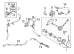
2000 Toyota Avalon Pump Assembly, Vane
Part Number: 44320-07012$299.96 MSRP: $428.28You Save: $128.32 (30%)Product Specifications- Other Name: Pump Assembly, L/Pulley; Power Steering Pump
- Manufacturer Note: (L)
- Replaces: 44320-33110, 44320-33111, 44320-07010, 44320-07011
- Part Name Code: 44320
- Item Weight: 6.30 Pounds
- Item Dimensions: 7.8 x 6.0 x 4.8 inches
- Condition: New
- Fitment Type: Direct Replacement
- SKU: 44320-07012
- Warranty: This genuine part is guaranteed by Toyota's factory warranty.
2000 Toyota Avalon Power Steering Pump
Looking for affordable OEM 2000 Toyota Avalon Power Steering Pump? Explore our comprehensive catalogue of genuine 2000 Toyota Avalon Power Steering Pump. All our parts are covered by the manufacturer's warranty. Plus, our straightforward return policy and speedy delivery service ensure an unparalleled shopping experience. We look forward to your visit!
2000 Toyota Avalon Power Steering Pump Parts Q&A
- Q: How to service and repair the power steering pump on 2000 Toyota Avalon?A: Service and repair of the power steering pump starts with PS vane pump rotating torque measurement to verify pump rotation quality without unusual noises and confirm maximum allowed torque of 0.3 Nm (2.8 kgf.cm, 2.4 inch lbs.). Special Service Tool: 09960-10010 (09962-01000, 09963-01000) should be used to stop the pulley from rotating before users loosen the nut and remove the pulley from the vane pump shaft. The next stage requires workers to eliminate the front and rear brackets by extracting three bolts and two nuts then the suction port union needs its bolt and O-ring removed. Start by disconnecting the pressure port union followed by removal of the flow control valve and spring and O-ring from this union. The wave washer and side plate with gasket and cam ring can be taken out after removing four bolts and two O-rings from the rear housing. Similarly extract the vane pump rotor accompanied by ten vane plates while keeping them secure from dropping. The front housing requires removal of its vane pump shaft and two straight pins. The vane pump shaft bushing oil clearance measurement demands a micrometer and caliper gauge to check against the 0.03 - 0.05 mm (0.0012 - 0.0020 inch) standard range and less than 0.07 mm (0.0028 inch) maximum clearance; replace both parts if needed. Measure the vane pump rotor and vane plates for height and thickness and length which should not fall below 8.6 mm (0.339 inch), 1.397 mm (0.0550 inch) and 14.991 mm (0.5902 inch) respectively Check the groove clearance between the vane plate and rotor of the vane pump which should not exceed 0.035 mm (0.0014 inch) and use only replacement components marked similarly on the cam ring. To test the flow control valve insert power steering fluid and verify its smooth descent into the hole before applying compressed air pressure between 392 and 490 kPa (4 to 5 kgf/cm2, 57 to 71 psi) to check for leakage. If leaks occur replace with valves marked A, B, C, D, E, or F. Measure the spring length with vernier calipers and keep the free length at least 32.3 mm (1.272 inch) before replacement if the measurement falls outside specification. Take care to remove the oil seal with a screwdriver covered in vinyl tape before properly inserting a new oil seal lip which should be coated in power steering fluid using Special Service Tool: 09950-60010 (09951-00330), 09950-70010 (09951-07100) while paying attention to the correct installation direction. Assemble the system by applying power steering fluid to marked components and inserting two straight pins with plastic hammering before adding the vane pump shaft followed by the cam ring with outer inscribed facing up and the vane pump rotor with similar marking at the front and a new snap ring. The installation order begins with the 10 vane plates that have their round end pointing outside followed by a new gasket then the side plate should be positioned against the straight pins. After inserting the wave washer protrusions into the side plate slots, apply power steering fluid to 2 new O-rings before placing them on the rear housing which must be tightened using 4 bolts at 17 Nm (170 kgf.cm, 12 ft. lbs.). Secure the pressure port union with 83 Nm torque after installing a new O-ring which received power steering fluid coating in the correct direction with the spring and flow control valve. Following installation of the suction port union and new O-ring with 13 Nm (130 kgf.cm, 9 ft. lbs.) torque, proceed to attach the front and rear brackets using 3 bolts and 2 nuts at 43 Nm (440 kgf.cm, 32 ft. lbs.). The vane pump shaft requires the pulley and its nut installation along with Special Service Tool: 09960-10010 (09962-01000, 09963-01000), which stops the pulley from turning before applying 44 Nm (450 kgf.cm, 33 ft. lbs.) torque onto the nut for measurements of PS vane pump rotating torque.
Related 2000 Toyota Avalon Parts
 2000 Toyota Avalon Power Steering Hose
 2000 Toyota Avalon Steering Wheel
 2000 Toyota Avalon Drag Link
 2000 Toyota Avalon Power Steering Control Valve
 2000 Toyota Avalon Power Steering Reservoir
 2000 Toyota Avalon Rack And Pinion
 2000 Toyota Avalon Rack and Pinion Boot
 2000 Toyota Avalon Steering Column Cover
 2000 Toyota Avalon Steering Gear Box
 2000 Toyota Avalon Tie Rod End
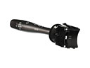 2000 Toyota Avalon Turn Signal Switch
 2000 Toyota Avalon Wiper Switch