×
ToyotaParts- Hello
- Login or Register
- Quick Links
- Live Chat
- Track Order
- Parts Availability
- RMA
- Help Center
- Contact Us
- Shop for
- Toyota Parts
- Scion Parts
My Garage
My Account
Cart
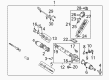
OEM 2000 Toyota Avalon Rack And Pinion
Steering Rack And Pinion- Select Vehicle by Model
- Select Vehicle by VIN
Select Vehicle by Model
orMake
Model
Year
Select Vehicle by VIN
For the most accurate results, select vehicle by your VIN (Vehicle Identification Number).
2 Rack And Pinions found

2000 Toyota Avalon Rack, Front
Part Number: 44204-07010$401.78 MSRP: $588.81You Save: $187.03 (32%)Ships in 1-3 Business DaysProduct Specifications- Other Name: Rack Sub-Assembly, Power; Rack And Pinion Rack Gear, Front; Steering Gearbox; Steering Rack; Rack Sub-Assembly, Power Steering
- Position: Front
- Part Name Code: 44204
- Item Weight: 5.50 Pounds
- Item Dimensions: 33.3 x 3.2 x 2.8 inches
- Condition: New
- Fitment Type: Direct Replacement
- SKU: 44204-07010
- Warranty: This genuine part is guaranteed by Toyota's factory warranty.
 Product Specifications
- Other Name: Gear Assembly, Power Steering; Steering Gearbox
- Replaces: 44250-07061, 44250-07040, 44250-06120
- Part Name Code: 44250
- Item Weight: 21.40 Pounds
- Item Dimensions: 59.9 x 12.1 x 7.2 inches
- Condition: New
- Fitment Type: Direct Replacement
- SKU: 44250-07062
- Warranty: This genuine part is guaranteed by Toyota's factory warranty.
2000 Toyota Avalon Rack And Pinion
Looking for affordable OEM 2000 Toyota Avalon Rack And Pinion? Explore our comprehensive catalogue of genuine 2000 Toyota Avalon Rack And Pinion. All our parts are covered by the manufacturer's warranty. Plus, our straightforward return policy and speedy delivery service ensure an unparalleled shopping experience. We look forward to your visit!
2000 Toyota Avalon Rack And Pinion Parts Q&A
- Q: How to service and repair the Rack And Pinion on 2000 Toyota Avalon?A: The first step to servicing the rack and pinion consists of utilizing Special Service Tool: 09612-00012 to clamp the Rack And Pinion assembly inside a vise without exceeding the recommended tightening force. Service Tool 09633-00020 should be used to remove the 2 turn pressure tubes along with the 4 O-rings. Record a mark on both tie rod ends and rack ends before uninstalling the lock nuts and rod ends on all sides. The service requires clamps to be loosened with a screwdriver to detach the clips and rack boots while paying attention to avoid damaging the boots and marking the parts for orientation. Use a screwdriver with hammer to unstake claw washers while holding the rack and pinion with a 24 mm spanner before removing the rack ends with Special Service Tool: 09922-10010 according to proper directional steps. Special Service Tools 09922-10010, 09631-10021 enable technicians to remove the rack guide spring cap lock nut followed by the rack guide spring cap. Afterward, they can remove the rack guide spring and sub-assembly. The dust seal and control valve housing should be removed along with the assembly using Special Service Tool: 09616-00010 and its components while documenting positions for future reassembly. Press the control valve assembly with its oil seal through the hole but always cover the oil seal lip with vinyl tape. Use Special Service Tool: 09631-10021 to rotate the cylinder end stopper clockwise and counterclockwise until you can remove it. After that, take off the rack housing No. 2 bracket and grommet. The rack and pinion removal process requires use of a brass bar with hammer to extract the bushing and O-ring. Install the oil seal into Special Service Tool: 09950-60010 (09951-00290), 09950-70010 (09951-07360) to extract it from the press. Check the rack and pinion for runout while inspecting wear because maximum rack runout should not exceed 0.03 mm (0.0012 inch). You must use Special Service Tool: 09950-60010 (09951-00250), 09950-70010 (09951-07200) with power steering fluid-coated new oil seal lips before pressing it into place. Additionally you should replace bearings while coating new bearings with molybdenum disulfide lithium base grease. To proceed with the oil seal replacement from the bushing use Special Service Tool: 09527-20011 but maintain the bushing in good condition. The assembly process requires new teflon rings and O-rings that must be placed correctly through Special Service Tool: 09631-20081 without damaging the teflon ring groove. After application of power steering fluid or grease to parts the assembly requires a new oil seal to be installed with correct orientation before placing the rack and pinion inside the rack housing while protecting the oil seal lip. The bushing assembly requires installation with a new O-ring oriented correctly before receiving the finishing cylinder end stopper with its new wire. Special Service Tool: 09631-12071 must be used for an air-tightness test to create a 30-second vacuum with 53 kPa (400 mm Hg, 15.75 inch Hg) pressure. Install the rack housing No. 2 bracket together with grommet followed by control valve assembly while performing oil seal and teflon rings protection. The control valve housing must get a new gasket before screwing in the bolts to 18 Nm (185 kgf.cm, 13 ft. lbs.) and self-locking nut to 25 Nm (250 kgf.cm, 18 ft. lbs.). The rack housing cap and dust seal should go together with sealant before reaching torque levels of 59 Nm (600 kgf.cm, 43 ft. lbs.) while adding cap staking. Proceed by installing the rack guide sub-assembly with spring and cap and adjust the total preload level using Special Service Tool: 09631-10021 within the 0.8 - 1.4 Nm (8 - 14 kgf.cm, 6.9 - 12.2 inch lbs.) range. The install process for the rack guide spring cap lock nut includes applying sealant then torquing it to 50 Nm (513 kgf.cm, 37 ft. lbs.) before reevaluating the preload. Complete the procedure by torquing lock nuts to 74 Nm (750 kgf.cm, 54 ft. lbs.) while aligning rack ends correctly, then place the 2-turn pressure tubes with new O-rings and torquing to 10 Nm (102 kgf.cm, 7 ft. lbs.).
Related 2000 Toyota Avalon Parts
 2000 Toyota Avalon Power Steering Hose
 2000 Toyota Avalon Power Steering Pump
 2000 Toyota Avalon Steering Wheel
 2000 Toyota Avalon Drag Link
 2000 Toyota Avalon Power Steering Control Valve
 2000 Toyota Avalon Power Steering Reservoir
 2000 Toyota Avalon Rack and Pinion Boot
 2000 Toyota Avalon Steering Angle Sensor
 2000 Toyota Avalon Steering Column Cover
 2000 Toyota Avalon Steering Gear Box
 2000 Toyota Avalon Steering Shaft
 2000 Toyota Avalon Tie Rod End