×
ToyotaParts- Hello
- Login or Register
- Quick Links
- Live Chat
- Track Order
- Parts Availability
- RMA
- Help Center
- Contact Us
- Shop for
- Toyota Parts
- Scion Parts
My Garage
My Account
Cart
OEM 2006 Toyota Avalon Power Steering Pump
Power Steering Pump Unit- Select Vehicle by Model
- Select Vehicle by VIN
Select Vehicle by Model
orMake
Model
Year
Select Vehicle by VIN
For the most accurate results, select vehicle by your VIN (Vehicle Identification Number).
1 Power Steering Pump found


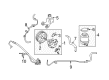
2006 Toyota Avalon Power Steering Pump
Part Number: 44310-07040$317.57 MSRP: $453.41You Save: $135.84 (30%)Ships in 1-2 Business DaysProduct Specifications- Other Name: Pump Assembly, Vane; Pump
- Part Name Code: 44320
- Item Weight: 10.90 Pounds
- Item Dimensions: 8.2 x 6.0 x 5.8 inches
- Condition: New
- Fitment Type: Direct Replacement
- SKU: 44310-07040
- Warranty: This genuine part is guaranteed by Toyota's factory warranty.
2006 Toyota Avalon Power Steering Pump
Looking for affordable OEM 2006 Toyota Avalon Power Steering Pump? Explore our comprehensive catalogue of genuine 2006 Toyota Avalon Power Steering Pump. All our parts are covered by the manufacturer's warranty. Plus, our straightforward return policy and speedy delivery service ensure an unparalleled shopping experience. We look forward to your visit!
2006 Toyota Avalon Power Steering Pump Parts Q&A
- Q: How to service and repair the power steering pump on 2006 Toyota Avalon?A: The repair process starts with front wheel RH removal and power steering fluid drainage followed by front fender apron seal RH removal and fan and generator V belt detaching. Then disconnect the oil reservoir to pump hose No.1 using its clip. Next detach the pressure feed tube assembly through bolt removal and clamp deinstalling. Finally remove the gasket. The service begins by removing the front fender apron seal RH and the fan and generator V belt followed by disconnecting the oil reservoir to pump hose No.1 with the clip removal. After disconnecting the union bolt and clamp bolt both must be removed before taking out the pressure feed tube assembly gasket. Remove two bolts which secure the vane pump assembly after disconnecting its power steering oil pressure switch connector. Individual the vane pump assembly in a vise with the tool SST 09630-00014 (09631-00132) then remove the power steering suction port union after taking out its bolt together with the O-ring. Disconnect the pressure port union along with its O-ring then separate the flow control valve and compression spring. Remove the power steering oil pressure switch alongside its O-ring and substitute the components if the O-ring shows signs of damage. Remove the vane pump housing rear by unbolting its four screws and O-ring. Apply two screwdrivers to unlink the snap ring followed by shifting the w/pulley shaft sub-assembly. Establish a cleaning workstation by removing ten vane pump plates and the vane pump rotor and the vane pump cam ring and the vane pump side plate front and their O-rings. Guard the vane pump housing oil seal while extracting it away from the housing front. Measure the oil clearance between the vane pump shaft and its bush that sit inside the housing front. The measurement should be less than 0.07 mm (0.0028 inch). Assess the thickness of vane pump plates as they should range from 1.405 to 1.411 mm (0.05531 to 0.05555 inch) and verify the vane pump rotor groove clearance with vane plates operates within 0.03 mm (0.0012 inch) limits. Apply power steering fluid to the flow control valve before inserting it into its designated hole. A compressed air leak test should follow. Check the compression spring free length which should measure at least 36.9 mm (1.453 inch). The vane pump assembly requires replacement in case the pressure port union shows signs of damage. You must replace the new vane pump housing oil seal with power steering fluid coating using SST 09950-60010 (09951-00280) and 09950-70010 (09951-07100) and verify proper orientation. Insert the w/pulley shaft sub-assembly through the vane pump housing while maintaining attention for oil seal lip damage. Prepare new O-rings by applying power steering fluid before placing them on the vane pump housing along its front and side plate front. Align the dent properly when doing so. The vane pump cam ring requires installation with the inscribed mark directed upward before placing the vane pump rotor that needs power steering fluid application. The w/pulley shaft sub-assembly needs ten vane pump plates with round ends facing out before securing it with a new snap ring. The tool must receive power steering fluid coating before setup into the vane pump housing rear position with straight pin alignment while using four bolts for 22 Nm (224 kgf-cm, 16 ft. lbs.) tightening torque. Check the pump moves without any noises while also testing the pulley rotating torque for less than 0.27 Nm (2.8 kgf-cm, 2.4 ft. lbs.) through temporary installation of a 10 mm x 1.25 mm thread pitch service bolt with 50 mm length. The installation of the power steering oil pressure switch requires a new O-ring and power steering fluid coating before torquing it to 21 Nm (214 kgf-cm, 16 ft. lbs.). First apply power steering fluid onto the compression spring and flow control valve then position them within the system and finally prepare a new O-ring with power steering fluid before fitting it to the pressure port union that requires a tightening torque of 69 Nm (704 kgf-cm, 51 ft. lbs.). After installing a new O-ring equipped with power steering fluid to the power steering suction port union the technician must tighten the bolt to 12 Nm (122 kgf-cm, 9 ft. lbs.) before proceeding with vane pump assembly installation at 43 Nm (439 kgf-cm, 32 ft. lbs.). The pressure feed tube assembly requires a new gasket for installation followed by tightening its union bolt to 52 Nm (525 kgf-cm, 38 ft. lbs.) and securing the clamp bolt at 9.8 Nm (100 kgf-cm, 87 inch lbs.). Install the front fender apron seal RH at 103 Nm along with pump hose No.1 to the oil reservoir while adding front wheel RH and fan and generator V belt before bleeding power steering fluid. As the final step ensure you bleed power steering fluid while conducting a leak inspection.
Related 2006 Toyota Avalon Parts
 2006 Toyota Avalon Power Steering Hose
 2006 Toyota Avalon Steering Wheel
 2006 Toyota Avalon Drag Link
 2006 Toyota Avalon Power Steering Control Valve
 2006 Toyota Avalon Power Steering Reservoir
 2006 Toyota Avalon Rack And Pinion
 2006 Toyota Avalon Rack and Pinion Boot
 2006 Toyota Avalon Steering Column Cover
 2006 Toyota Avalon Steering Gear Box
 2006 Toyota Avalon Steering Shaft
 2006 Toyota Avalon Tie Rod End
 2006 Toyota Avalon Wiper Switch