×
ToyotaParts- Hello
- Login or Register
- Quick Links
- Live Chat
- Track Order
- Parts Availability
- RMA
- Help Center
- Contact Us
- Shop for
- Toyota Parts
- Scion Parts
My Garage
My Account
Cart
OEM 2007 Toyota Avalon Rack And Pinion
Steering Rack And Pinion- Select Vehicle by Model
- Select Vehicle by VIN
Select Vehicle by Model
orMake
Model
Year
Select Vehicle by VIN
For the most accurate results, select vehicle by your VIN (Vehicle Identification Number).
1 Rack And Pinion found

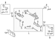
2007 Toyota Avalon Steering Gear
Part Number: 44250-07101$676.90 MSRP: $992.01You Save: $315.11 (32%)Ships in 1-3 Business DaysProduct Specifications- Other Name: Gear Assembly, Power Steering; Rack and Pinion Assembly; Steering Gearbox; Gear Assembly; Gear Assembly, Power Steering(For Rack & Pinion)
- Replaces: 44250-07100
- Part Name Code: 44250
- Item Weight: 22.30 Pounds
- Item Dimensions: 50.7 x 10.9 x 6.6 inches
- Condition: New
- Fitment Type: Direct Replacement
- SKU: 44250-07101
- Warranty: This genuine part is guaranteed by Toyota's factory warranty.
2007 Toyota Avalon Rack And Pinion
Looking for affordable OEM 2007 Toyota Avalon Rack And Pinion? Explore our comprehensive catalogue of genuine 2007 Toyota Avalon Rack And Pinion. All our parts are covered by the manufacturer's warranty. Plus, our straightforward return policy and speedy delivery service ensure an unparalleled shopping experience. We look forward to your visit!
2007 Toyota Avalon Rack And Pinion Parts Q&A
- Q: How to Service and Repair Rack and Pinion Power Steering Gear on 2007 Toyota Avalon?A: The power steering rack runout and tooth wear must be checked with a dial indicator to ensure maximum runout does not exceed 0.3mm (0.0118 inches). If runout exceeds this value the power steering rack and pinion assembly needs replacement. A thorough check of the rack surface must be performed to determine any wear or damage which would require an assembly replacement. Apply power steering fluid on the first new O-ring as you install it onto the rack and pinion but coat the new oil seal with power steering fluid before its placement on the rack and pinion. Use power steering fluid to coat the lip of the power steering cylinder tube oil seal before employing special service tool 09950-60010 (along with 09951-00420, 09951-00250, 09952-06010) and 09950-70010 (with 09951-07360) as well as a press for installation. Provide power steering fluid to the rack teeth ends and fasten special service tool: 09631-33010 to the rack and pinion. Subsequently coat the tool and new oil seal with power steering fluid before installing the rack inside the rack housing while using the tool. First coat the new rack bush oil seal lip with power steering fluid followed by installation using special service tool: 09950-60010 (09951-00400), 09950-70010 (09951-07100) and a press. Correct installation is essential in this step. Install the rack bush in the rack housing after applying new O-rings to it while securing the rack and pinion end with vinyl tape to protect the oil seal. Use the installation hole on the cylinder end stopper wire to insert a new wire into the rack housing slot before turning the stopper counterclockwise in a range from 450 degrees to 50 degrees. During the air tightness test use special service tool: 09631-12071 on the rack housing then apply a vacuum of 53 kPa (398 mmHg, 15.65 in. Hg) for 30 seconds before checking the vacuum pressure. Preparation includes grease application to the control valve upper bearing followed by power steering fluid coating of a new oil seal lip and the installation using special service tool: 09950-70010 (09951-07150), 09950-60010 (09951-00180, 09952-06010, 09951-00320) and a press to achieve proper direction. The installation of the control valve upper bearing requires the use of special service tool: 09950-70010 (09951-07150), 09950-60010 (09951-00180, 09952-06010, 09951-00340) together with a press equipment. Four new valve spacers need expansion before receiving power steering fluid coatings which enables their installation on the control valve while special service tool: 09631-20081 carefully fits the spacers onto the control valve before valve placement into the valve housing with spacer and lip protection. Ease the installation of a new oil seal lip by coating it with power steering fluid before using special service tool: 09612-22011 and a press to complete the task. Apply grease to both the needle roller bearing of the rack housing and the serrated part of the control valve then set the control valve and new gasket to the control valve housing with two bolts torqued to 20 N m (204 kgf cm, 15 ft. lbf) while holding special service tool: 09616-00011 steady. Using special service tool: 09616-00011 stabilize the control valve as you install a new lock nut and reach 25 N m (250 kgf cm, 18 ft. lbf) torque. Subsequently apply sealant (Part No. 08833-00080, THREE BOND 1344, LOCTITE 242 or equivalent) to 2 or 3 threads of the rack housing cap before attaching it with a 27 mm socket wrench torque of 54 N m (546 kgf cm, 40 ft. lbf). Complete the installation by punching and hammering the cap and the rack guide contact surface requires grease application before installing the rack guide along with its compression spring. Additionally, sealant should be applied to 2 or 3 threads of the rack guide spring cap followed by cap installation. A temporary installation of the RH and LH rack end sub-assemblies will protect oil seals from damage before torquing the rack guide spring cap to 25 N m (250kgf cm, 18 ft. lbf). Finish the installation by loosening the cap and rotating the control valve one or two times to the left and right. Adjust the rack guide spring cap while observing the compression spring behavior until it stops functioning before securing it at a preload between 1.2 to 1.5 N m (12.2 to 15.3 kgf cm, 10.6 to 13.3 in. lbf). Amazingly, this is a step that requires temporary installation of the rack guide spring cap lock nut along with its thread sealant application to 2-3 threads. Then torque it to 48 N m (487 kgf cm, 35 ft. lbf) with the rack guide spring cap securely held. After preload verification, workers must first remove the RH and LH rack end sub-assembly followed by MP grease application on the control valve shaft before vinyl tape installation on the control valve spline. They will then install the dust cover assembly. Equal the LH and RH rack end sub-assembly using special service tool: 09922-10010 with a torque of 58 N m (586 kgf cm, 42 ft. lbf) while momentarily installing them before hammer-staking the claw washers with a brass bar to avoid striking the rack and pinion. Before installation, ensure that the holes of the rack and pinion ends are clear from grease deposits. Then apply silicon grease inside rack boot No.2's small opening before placing it into the rack housing groove without causing damage to the boot. After applying special service tool 09521-24010 to rack boot No.2 perform the same clamp clearance testing then proceed with the same procedure using rack boot No.1. Fasten the two boot clips using pliers before connecting the tie rod assembly LH to the steering knuckle LH using the castle nut. Torque it to 49 N m (500 kgf cm, 36 ft. lbf) and use a new cotter pin while tightening the nut as needed. Follow the same process for the RH side to assemble the steering intermediate shaft assembly through matchmark alignment before installing the bolt to a torque of 35 N m (360 kgf cm, 26 ft. lbf). Then bleed the power steering fluid while checking for fluid loss before adding new fluid with the correct amount. Install the front fender apron seals LH and RH and put on the front wheel before inspecting front wheels and wheel alignment.
Related 2007 Toyota Avalon Parts
 2007 Toyota Avalon Power Steering Hose
 2007 Toyota Avalon Power Steering Pump
 2007 Toyota Avalon Steering Wheel
 2007 Toyota Avalon Drag Link
 2007 Toyota Avalon Power Steering Control Valve
 2007 Toyota Avalon Power Steering Reservoir
 2007 Toyota Avalon Rack and Pinion Boot
 2007 Toyota Avalon Steering Angle Sensor
 2007 Toyota Avalon Steering Column
 2007 Toyota Avalon Steering Gear Box
 2007 Toyota Avalon Steering Shaft
 2007 Toyota Avalon Tie Rod End