×
ToyotaParts- Hello
- Login or Register
- Quick Links
- Live Chat
- Track Order
- Parts Availability
- RMA
- Help Center
- Contact Us
- Shop for
- Toyota Parts
- Scion Parts
My Garage
My Account
Cart
OEM Toyota Sienna Rack And Pinion
Steering Gear- Select Vehicle by Model
- Select Vehicle by VIN
Select Vehicle by Model
orMake
Model
Year
Select Vehicle by VIN
For the most accurate results, select vehicle by your VIN (Vehicle Identification Number).
13 Rack And Pinions found


Toyota Sienna Steering Gear Part Number: 45510-08020
$567.15 MSRP: $831.16You Save: $264.01 (32%)Ships in 1-3 Business DaysToyota Sienna Steering Gear Part Number: 45510-08010
$567.15 MSRP: $831.16You Save: $264.01 (32%)Ships in 1-2 Business Days
Toyota Sienna Gear Assembly Part Number: 44250-08100
$699.72 MSRP: $1025.44You Save: $325.72 (32%)Ships in 1-3 Business Days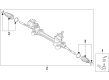
Toyota Sienna Rack Part Number: 44250-08090
$699.72 MSRP: $1025.44You Save: $325.72 (32%)Ships in 1-3 Business DaysToyota Sienna Gear Assembly Part Number: 44250-08080
$699.72 MSRP: $1025.44You Save: $325.72 (32%)Ships in 1-3 Business DaysToyota Sienna Gear Assembly Part Number: 44250-08110
$740.12 MSRP: $1084.66You Save: $344.54 (32%)
Toyota Sienna Rack Part Number: 44204-08010
$322.10 MSRP: $459.89You Save: $137.79 (30%)Ships in 1-3 Business Days
Toyota Sienna Gear Assembly, Electric Part Number: 44250-08111
$953.84 MSRP: $1397.87You Save: $444.03 (32%)Ships in 1-2 Business DaysToyota Sienna Gear Assembly, Electric Part Number: 44250-08101
$953.84 MSRP: $1397.87You Save: $444.03 (32%)Ships in 1-2 Business DaysToyota Sienna Gear Assembly, Electric Part Number: 44250-08081
$953.84 MSRP: $1397.87You Save: $444.03 (32%)Ships in 1-2 Business Days


Toyota Sienna Steering Gear Part Number: 44250-08041
$488.83 MSRP: $716.40You Save: $227.57 (32%)
Toyota Sienna Steering Gear Part Number: 44250-08020
Toyota Sienna Steering Gear Part Number: 44250-08010
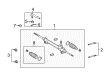
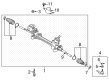
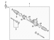
Toyota Sienna Rack And Pinion
Choose genuine Rack And Pinion that pass strict quality control tests. You can trust the top quality and lasting durability. Shopping for OEM Rack And Pinion for your Toyota Sienna? Our website is your one-stop destination. We stock an extensive selection of genuine Toyota Sienna parts. The price is affordable so you can save more. It only takes minutes to browse and find the exact fit. Easily add to cart and check out fast. Our hassle-free return policy will keep you stress-free. We process orders quickly for swift delivery. Your parts will arrive faster, so you can get back on the road sooner.
The Toyota Sienna Rack And Pinion is a critical part that transforms the rotary movement generated by the driver when turning the steering wheel into linear motion of the front wheels. This mechanism is called the rack and pinion; it is made of gears positioned in a metal tube which is fixed on the car's chassis. This is a part of the steering system where there is a transmitting shaft from the steering wheel and the pinion gear is engaged to the rack gear which is housed in the tube and by the turning of the pinion gear the rack gear is forced towards the required direction hence steering of the vehicle. Present day Sienna cars employ power assist, where rack and pinion mechanisms are employed and are assisted by hydraulics by way of fluid pressure. Problems related to the Steering Rack may include; spoilt seals, leaks or worn gears, the likely symptoms may include; stiff steering, grinding sounds or wandering. If the steering wheel shakes unusually or is loose, or the car has a tendency to veer left or right on a calm road, then it AutoPro may recommend that you get a new rack and pinion assembly. Still, the rack and pinion system in Toyota Sienna vehicles is crucial for steering and having a good feel of the road without being affected by the problem highlighted above.
Toyota Sienna Rack And Pinion Parts and Q&A
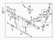
- Q: How to service and repair the Rack And Pinion on Toyota Sienna?A:The Rack And Pinion assembly needs to be placed in a vise using Special Service Tool: 09612-00012 but tightening too much should be avoided. The 2 turn pressure tubes require Special Service Tool: 09023-38200 for removal while extracting the 4 O-rings. First note the positions of the tie rod ends and rack ends before loosening and removing the lock nuts and tie rod ends from both sides. A screwdriver should be used to loosen clamps before extracting RH and LH clips, rack boots and clamps while protecting their boot integrity. To remove rack ends your helper should use Special Service Tool: 09922-10010 while using a 24 mm spanner to hold the rack and pinion when unstaking claw washers using a screwdriver along with a hammer. Use Special Service Tool: 09922-10010 to remove the rack guide spring cap lock nut so you can extract the rack guide spring cap and rack guide spring as well as rack guide sub-assembly using a 21 mm hexagon wrench. Use Special Service Tool: 09616-00011 to disassemble the self-locking nut before removing the dust cover with control valve housing and control valve assembly, while marking matchmarks and removing the gasket. Wind vinyl tape to the control valve shaft to protect the oil seal lip before pressing out the control valve assembly with the oil seal while inserting a shop rag between valve housing and blocks. First remove the oil seal from the control valve assembly before extracting the rack and pinion No. 2 bracket and grommet by marking their matchmarks while prying the clamp. Use Special Service Tool: 09631-10021 to turn the cylinder end stopper clockwise and reveal the wire end before removing it through counterclockwise rotation. Use a brass bar and hammer to strike the rack and pinion until all components such as the bushing and O-ring fall out. The installation requires Special Service Tool: 09950-60010 (09951-00290), 09950-70010 (09951-07360) to push out the oil seal. Check the rack and pinion for maximum runout using measuring tools. The limit should not exceed 0.03 mm (0.0118 inch). Install the new oil seal after coating its lip with the power steering fluid using Special Service Tool: 09950-60010 (09951-00180, 09951-00320, 09952-06010) or 09950-70010 (09951-07200). The replacement process requires new bearings to receive molybdenum disulfide lithium base grease coating. New oil seals from bushings require installation through Special Service Tools 09527-20011 and 09612-24014 (09613-22011). Before insertion use TOOL 09950-60010 (09951-00240 and 09951-00400 and 09952-06010) to press the new oil seal while coating the lip with power steering fluid. Reinstall the teflon ring and O-ring from the rack and pinion while keeping the groove intact then put in new components that received power steering fluid coating. The technician should replace teflon rings used in the control valve assembly after expanding them by dipping them in power steering fluid before assembly. To rebuild the assembly place power steering fluid and molybdenum disulfide lithium base grease on the mentioned components before installing the oil seal in its proper orientation and rack and pinion with Special Service Tool: 09631-33010. Handle the oil seal lip with extreme care. Position the bushing while using a new O-ring treated with power steering fluid and validate its correct orientation. The installation holes for the wire require proper alignment before installing the cylinder end stopper. Use Special Service Tool: 09631-12071 to conduct an air tightness test where vacuum pressure reaches 53 kPa (400 mm Hg, 15.75 inch Hg) for 30 seconds. Fasten the rack and pinion No. 2 bracket and insert its grommet while matching the alignment indicators before tightening the clamp. The control valve assembly goes next while avoiding oil seal lip damage and using Special Service Tool: 09612-22011 for installing the oil seal correctly. The control valve assembly needs to be installed with the housing after putting a fresh gasket in place and aligning matchmarks before torquing the hardware to 18 Nm (180 kgf-cm, 13 ft. lbs.) with two bolts. To install the self-locking nut users must use Special Service Tool: 09616-00011 at a torque setting of 25 Nm (250 kgf-cm, 18 ft. lbs.) before adding the dust cover followed by the rack and pinion cap after applying sealant on the threads to a torque of 59 Nm (600 kgf-cm, 43 ft. lbs.) alongside part staking procedures. Attach the rack guide sub-assembly, rack guide spring and rack guide spring cap while sealing the threads with the specified adhesive. To achieve total preload adjustment install the RH and LH rack ends until torquing the rack guide spring cap to 25 Nm (250 kgf-cm, 18 ft. lbs.) then return the cap 12 degrees while adjusting preload to 0.8 - 1.4 Nm (8 - 14 kgf-cm, 6.9 - 12.2 inch lbs.). Apply sealant to the rack guide spring cap lock nut before torquing it to 50 Nm (510 kgf-cm, 37 ft. lbs.) while checking the total preload again. Complete the installation by first torquing the rack ends to 60 Nm (610 kgf-cm, 44 ft. lbs.) after checking claw washers' alignment within rack and pinion grooves. Lastly, stake the washers then place on RH and LH rack boots, clamps, and clips ensuring the hole is free before tightening clamps with Special Service Tool: 09521-24010.
- Q: How to install the rack and pinion power steering gear assembly on Toyota Sienna?A:The rack and pinion power steering rack and pinion assembly needs to be mounted with two bolts and nuts torqued to 70 Nm (714 kg-cm, 52 ft. lbs.). Proceed with tube assembly installation to the power steering rack and pinion assembly before placing the clip. The installation requires Special Service Tool: 09023-12701 to connect the return tube assembly where 22.5 Nm (229 kg-cm, 17 ft. lbs.) torque must be applied from a torque wrench with 300 mm (11.81 inch) fulcrum length and the tool must align parallel to the wrench. The tube clamp installation requires the use of bolt and nut while torquing them to 9.8 Nm (100 kg-cm, 87 inch lbs.). Occupy the front stabilizer bracket No.1 LH using 2 bolts that require a torque rate of 17 Nm (173 kg-cm, 12 ft. lbs.). Do the same step for front stabilizer bracket No.1 RH. The installation of front stabilizer link assemblies needs to be performed on both left-hand and right-hand sides. Blend the matchmarks between the power steering rack and pinion assembly and steering intermediate shaft before bolting it with a torque of 36 Nm (367 kg-cm, 27 ft. lbs.) while also verifying a tight fitting of the dust cover. The front wheels must be installed with tie rod assemblies on both left-hand and right-hand sides before torquing the front wheel to 103 Nm (1,050 kg-cm, 76 ft. lbs.). The conclusion of the procedure requires checking the center front wheel followed by inspecting the steering wheel center point and performing power steering fluid checks for leakage with measurements for the front wheel alignment.


Related Toyota Sienna Parts
 Toyota Sienna Steering Wheel
 Toyota Sienna Ignition Switch
 Toyota Sienna Power Steering Hose
 Toyota Sienna Power Steering Reservoir
 Toyota Sienna Steering Angle Sensor
 Toyota Sienna Drag Link
 Toyota Sienna Power Steering Control Valve
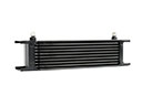 Toyota Sienna Power Steering Cooler
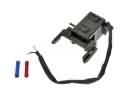 Toyota Sienna Shift Interlock Solenoid
 Toyota Sienna Steering Column Cover
 Toyota Sienna Steering Gear Box
 Toyota Sienna Tie Rod End