×
ToyotaParts- Hello
- Login or Register
- Quick Links
- Live Chat
- Track Order
- Parts Availability
- RMA
- Help Center
- Contact Us
- Shop for
- Toyota Parts
- Scion Parts
My Garage
My Account
Cart
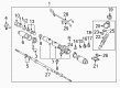
OEM 2003 Toyota Sienna Rack And Pinion
Steering Rack And Pinion- Select Vehicle by Model
- Select Vehicle by VIN
Select Vehicle by Model
orMake
Model
Year
Select Vehicle by VIN
For the most accurate results, select vehicle by your VIN (Vehicle Identification Number).
2 Rack And Pinions found

2003 Toyota Sienna Rack
Part Number: 44204-08010$322.10 MSRP: $459.89You Save: $137.79 (30%)Ships in 1-3 Business DaysProduct Specifications- Other Name: Rack Sub-Assembly, Power; Steering Gearbox; Steering Rack; Rack Sub-Assembly, Power Steering
- Part Name Code: 44204
- Item Weight: 5.50 Pounds
- Item Dimensions: 32.7 x 3.2 x 2.8 inches
- Condition: New
- Fitment Type: Direct Replacement
- SKU: 44204-08010
- Warranty: This genuine part is guaranteed by Toyota's factory warranty.
 Product Specifications
- Other Name: Gear Assembly, Power Steering; Rack and Pinion Assembly; Steering Gearbox; Rack & Pinion; Gear Assembly; Gear Assembly, Power Steering(For Rack & Pinion)
- Part Name Code: 44250
- Item Weight: 20.80 Pounds
- Item Dimensions: 40.2 x 13.0 x 7.4 inches
- Condition: New
- Fitment Type: Direct Replacement
- SKU: 44250-08020
- Warranty: This genuine part is guaranteed by Toyota's factory warranty.
2003 Toyota Sienna Rack And Pinion
Looking for affordable OEM 2003 Toyota Sienna Rack And Pinion? Explore our comprehensive catalogue of genuine 2003 Toyota Sienna Rack And Pinion. All our parts are covered by the manufacturer's warranty. Plus, our straightforward return policy and speedy delivery service ensure an unparalleled shopping experience. We look forward to your visit!
2003 Toyota Sienna Rack And Pinion Parts Q&A
- Q: How to disassemble the Rack And Pinion on 2003 Toyota Sienna?A: Place the rack and pinion assembly in a vise with special service tool: 09612-00012 and use special service tool: 09023-38200 plus the proper indentation to take off the two turn pressure tubes while removing the four O-rings. Label both tie rod end and rack end pieces before taking off the lock nuts that hold each end in place from the RH and LH sides. Repeat this process to remove the second set of parts on the opposite side. Detach the clamp with a screwdriver to remove RH and LH clips along with their boots and clamps at each side. Keep the boot safe during removal and label the RH and LH rack boots. Hold the rack and pinion with a 24 mm spanner and strike the claw washer with a screwdriver and hammer to disengage it from the rack end. Then take off the end using special service tool 09922-10010 on both sides. You can remove the rack guide spring cap lock nut using special service tool: 09922-10010. Then use a 21 mm hexagon wrench to take the rack guide spring cap off before removing the rack guide spring and assembly. Secure the end of the control valve shaft with special service tool 09616-00011 before loosening the self-locking nut. You can then remove the dust cover together with the control valve housing and control valve assembly. Mark the matchmarks and take off the gasket. Install vinyl tape to stop oil seal damage on the control valve shaft's serrations and push the control valve assembly with oil seal out while putting cloth between the valve housing and supports to avoid dropping it. Mark the rack housing components first before using a tool to pry off the clamp and separate the grommet. Twist the cylinder end stopper clockwise using special service tool: 09631-10021 until the wire end shows and turn it counterclockwise to take it out. Strike the bushing at the rack and pinion using a brass bar and hammer to extract the setup while you also take off the bushing O-ring and oil seal employing special service tool: 09950-60010 (09951-00290), 09950-70010 (09951-07360). Check the rack and pinion for movement deviations and wear marks while confirming that maximum runout stays below 0.03 mm (0.0118 inch) and examining the rear surface condition. When required install a new oil seal and bearing by first coating the oil seal lip with power steering fluid and then pressing it in together with special service tool: 09950-60010 (09951-00180 and 09951-00320) and 09950-70010 (09951-07200). Set the tools to precise installation standards. Use special service tool: 09950-60010 (09951-00340) and 09950-70010 (09951-07200) to install fresh bearings that you have lubricated with molybdenum disulfide lithium grease. Use special service tool 09950-70010 (09951-7200) to tap 2 bearings out from the rack housing and press out replacement bearings with special service tool: 09950-60010 (09951-00260) followed by the appropriate grease coating and pressing. Install special service tools 09527-20011 and 09612-24014 to remove and replace the oil seal from the bushing while taking care of the bushing. Afterward, use power steering fluid to coat a new oil seal lip before inserting it with special service tools 09950-60010 and 09951-00240 09951-00400, 09952-06010. Install the new O-ring on the rack and pinion with power steering fluid and stretch the Teflon ring before topping it up with fluid and setting it into position. Use special service tool: 09631-20081 to place 4 newly expanded Teflon rings carefully into the control valve assembly when replacing the rings. Reassemble while coating specific parts in power steering fluid or molybdenum disulfide lubricant with screwdriver applied to oil seal using special service tool 09950-60010 (09951-00240, 09951-00430, 09952-06010). Insert components in proper direction. Position the rack and pinion into the housing using special service tool: 09631-33010 and apply power steering fluid as you gently fit it into the rack housing. Put the bushing into place with a fresh O-ring treated in power steering fluid. Also normalize the bushing movement and protect the oil seal lip at the same time. Put the cylinder end stopper wire in its designated hole and apply a new wire before rotating the stopper 450 plus or minus 50 degrees with special service tool 09631-10021. Check air leakage in the rack housing using special service tool: 09631-12071 under 53 kPa of vacuum maintained for 30 seconds. Connect the No. 2 rack housing grommet and bracket by placing marks side to side and tightening the clamping mechanism afterwards. Press the oil seal into position using special service tool: 09612-22011 to avoid damaging the lip protectors. Install the control valve assembly in its correct direction. Fit the control valve housing onto its assembly and matchmarks while fixing it using 2 bolts at 18 Nm tightening. Install the self-locking nut at 25 Nm using special service tool: 09616-00011. Then mount the dust cover and rack housing cap using sealant (Part No. 08833-00080, THREE BOND 1344, LOCTITE 242 or equivalent) on 2 to 3 threads and tighten to 59 Nm with staked cap parts. Fit together rack guide sub-assembly with spring generator and cap while applying thread sealant to the cap threads and then place it temporarily. Use special service tool 09616-00011 to turn the control valve shaft after temporarily placing the rack guide spring cap to 25 Nm while keeping the cap at 12° angle. Turn the rack guide spring cap to have no effect then tighten it to obtain a 0.8 - 1.4 Nm (8 - 14 kgf-cm, 6.9 - 12.2 inch lbs.) pre-reload. Apply sealant to the rack guide spring cap lock nut, install it on the steering assembly for measurement, and apply 50 Nm (510 kgf-cm) torque through special service tool: 09922-10010 to check total preload. Finally, install the RH and LH claw washers and rack ends, ensuring alignment with the rack and pinion grooves, torque the rack end to 60 Nm (610 kgf-cm, 44 ft. lbs.) using special service tool: 09922-10010, stake the claw washer, and repeat for the other side, then install the RH and LH rack boots, clamps, and clips, ensuring no clogging in the rack and pinion hole, and tighten the clamp with special service tool: 09521-24010, repeating for the other side, and finally install the 2 turn pressure tubes with new O-rings coated in power steering fluid, using special service tool: 09023-38200 and torquing to 12 Nm (120 kgf-cm, 9 ft. lbs.).
Related 2003 Toyota Sienna Parts
 2003 Toyota Sienna Steering Wheel
 2003 Toyota Sienna Ignition Switch
 2003 Toyota Sienna Power Steering Hose
 2003 Toyota Sienna Power Steering Pump
 2003 Toyota Sienna Power Steering Reservoir
 2003 Toyota Sienna Rack and Pinion Boot
 2003 Toyota Sienna Drag Link
 2003 Toyota Sienna Power Steering Control Valve
 2003 Toyota Sienna Steering Column Cover
 2003 Toyota Sienna Steering Gear Box
 2003 Toyota Sienna Steering Shaft
 2003 Toyota Sienna Tie Rod End