×
ToyotaParts- Hello
- Login or Register
- Quick Links
- Live Chat
- Track Order
- Parts Availability
- RMA
- Help Center
- Contact Us
- Shop for
- Toyota Parts
- Scion Parts
My Garage
My Account
Cart
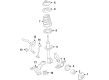
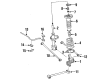
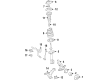
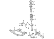
OEM Toyota Sway Bar Kit
Stabilizer Sway Bar Set- Select Vehicle by Model
- Select Vehicle by VIN
Select Vehicle by Model
orMake
Model
Year
Select Vehicle by VIN
For the most accurate results, select vehicle by your VIN (Vehicle Identification Number).
359 Sway Bar Kits found

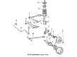
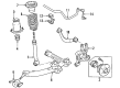
Toyota Stabilizer Bar, Rear
Part Number: 48812-AA050$98.94 MSRP: $138.88You Save: $39.94 (29%)Ships in 1-3 Business DaysProduct Specifications- Other Name: Bar, Stabilizer, Rear; Suspension Stabilizer Bar, Rear; Sway Bar
- Position: Rear
- Replaces: 48812-33170

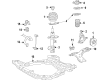
Toyota Stabilizer Bar, Rear
Part Number: 48805-02120$100.24 MSRP: $140.70You Save: $40.46 (29%)Ships in 1-3 Business DaysProduct Specifications- Other Name: Bar Sub-Assembly, Rear Stabilizer; Suspension Stabilizer Bar, Rear; Sway Bar; Bar, Stabilizer, Rear
- Position: Rear

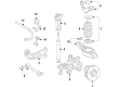
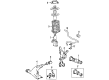
Toyota Stabilizer Bar, Rear
Part Number: 48812-06040$89.82 MSRP: $126.08You Save: $36.26 (29%)Ships in 1-3 Business DaysProduct Specifications- Other Name: Bar, Stabilizer, Rear; Sway Bar
- Position: Rear

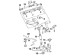
Toyota Stabilizer Bar, Rear
Part Number: 48812-06140$64.10 MSRP: $89.97You Save: $25.87 (29%)Ships in 1-3 Business DaysProduct Specifications- Other Name: Bar, Stabilizer, Rear; Suspension Stabilizer Bar, Rear; Sway Bar
- Manufacturer Note: MEXICO SPEC
- Position: Rear

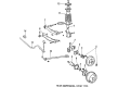
Toyota Stabilizer Bar, Front
Part Number: 48811-02030$119.72 MSRP: $169.48You Save: $49.76 (30%)Ships in 1-3 Business DaysProduct Specifications- Other Name: Bar, Stabilizer, Front; Suspension Stabilizer Bar, Front; Sway Bar
- Position: Front

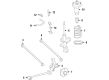
Toyota Stabilizer Bar, Rear
Part Number: 48812-12170$81.87 MSRP: $114.92You Save: $33.05 (29%)Ships in 1-3 Business DaysProduct Specifications- Other Name: Bar, Stabilizer, Rear; Sway Bar
- Position: Rear
- Replaces: 48812-02020

Toyota Stabilizer Bar, Front
Part Number: 48811-AA011$100.00 MSRP: $140.37You Save: $40.37 (29%)Ships in 1-3 Business DaysProduct Specifications- Other Name: Bar, Stabilizer, Front; Suspension Stabilizer Bar, Front; Sway Bar
- Position: Front
- Replaces: 48811-AA010

Toyota Stabilizer Bar, Front
Part Number: 48811-06050$128.65 MSRP: $182.12You Save: $53.47 (30%)Ships in 1-3 Business DaysProduct Specifications- Other Name: Bar, Stabilizer, Front; Suspension Stabilizer Bar, Front; Sway Bar
- Position: Front
- Replaces: 48811-33160

Toyota Stabilizer Bar, Rear
Part Number: 48805-12120$97.28 MSRP: $136.55You Save: $39.27 (29%)Ships in 1-3 Business DaysProduct Specifications- Other Name: Bar Sub-Assembly, Rear Stabilizer; Sway Bar; Bar, Stabilizer, Rear
- Position: Rear

Toyota Stabilizer Bar, Rear
Part Number: 48812-2B031$100.59 MSRP: $141.20You Save: $40.61 (29%)Ships in 1-3 Business DaysProduct Specifications- Other Name: Bar, Stabilizer, Rear; Suspension Stabilizer Bar, Rear; Sway Bar
- Position: Rear
- Replaces: 48812-2B030

Toyota Stabilizer Bar, Front
Part Number: 48811-02340$116.24 MSRP: $163.16You Save: $46.92 (29%)Ships in 1-3 Business DaysProduct Specifications- Other Name: Bar, Stabilizer, Front; Suspension Stabilizer Bar, Front; Sway Bar
- Position: Front
- Replaces: 48811-12B10
Toyota Stabilizer Bar, Front
Part Number: 48811-33060$83.65 MSRP: $117.41You Save: $33.76 (29%)Ships in 1-3 Business DaysProduct Specifications- Other Name: Bar, Stabilizer, Front; Suspension Stabilizer Bar, Front; Sway Bar
- Position: Front
Toyota Stabilizer Bar, Rear
Part Number: 48805-02110$92.54 MSRP: $129.89You Save: $37.35 (29%)Ships in 1-3 Business DaysProduct Specifications- Other Name: Bar Sub-Assembly, Rear Stabilizer; Sway Bar; Bar, Stabilizer, Rear
- Position: Rear

Toyota Stabilizer Bar, Front
Part Number: 48811-12A60$119.96 MSRP: $169.82You Save: $49.86 (30%)Ships in 1-3 Business DaysProduct Specifications- Other Name: Bar, Stabilizer, Front; Suspension Stabilizer Bar, Front; Sway Bar
- Position: Front
- Replaces: 48811-12A00, 48811-12A70


Toyota Stabilizer Bar, Rear
Part Number: 48812-06170$83.77 MSRP: $117.59You Save: $33.82 (29%)Ships in 1-3 Business DaysProduct Specifications- Other Name: Bar, Stabilizer, Rear; Suspension Stabilizer Bar, Rear; Sway Bar
- Position: Rear
- Replaces: 48812-33240

 Product Specifications
- Other Name: Bar, Stabilizer, Front; Suspension Stabilizer Bar, Front; Sway Bar
- Position: Front

 Product Specifications
- Other Name: Bar, Stabilizer; Sway Bar; Bar, Stabilizer, Front
- Position: Front
 Product Specifications
- Other Name: Bar, Stabilizer, Rear; Suspension Stabilizer Bar, Rear; Sway Bar
- Manufacturer Note: HANDLING PACKAGE
- Position: Rear

 Product Specifications
- Other Name: Bar Sub-Assembly, Rear Stabilizer; Sway Bar Link; Link
- Manufacturer Note: OD=15
- Position: Rear

 Product Specifications
- Other Name: Bar Sub-Assembly, Rear Stabilizer; Sway Bar
- Position: Rear
| Page 1 of 18 |Next >
1-20 of 359 Results
Toyota Sway Bar Kit
OEM parts deliver unmatched quality you can rely on. They pass extensive quality control inspections. Toyota produces them to the official factory specifications. This process helps prevent defects and imperfections. So you can get exceptional lifespan and a flawless fit. Need new OEM Toyota Sway Bar Kit? You'll love our wide selection of genuine options. Shop in minutes and skip the hunt. Our prices are unbeatable, you'll save time and money. It's easy to shop and find the right piece. Our committed customer service team gives professional help from start to finish. Every part includes a manufacturer's warranty. We ship quickly, your parts will arrive fast at your door.
Toyota Sway Bar Kit is a reduction in body roll which makes daily cornering of the car appear flat and in control. Toyota developed from a 1937 Japanese startup to a global giant by removing waste, empowering frontline employees, and stamping out defects as they occur, a requirement that keeps factories agile. Hybrids that drink less fuel, endure bad climates, and record insane odometer readings keep Toyota as a trusted brand to its clientele. Toyota stretched its TNGA platform to reduce center of gravity, distribute weight with greater intelligence, cut safer crush space, and have all its models, big and small, drive with the same assured response. Toyota has recently extended the range of plug-ins on the RAV4 and Prius, introduced less noisy motors, and demonstrated to drivers that efficiency and durability can be displayed on the same badge without any noticeable difference. Sway Bar Kit connects both left and right suspension arms and the torsion bar that twists during load, redistributing weight between outside and inside wheels and leveling the chassis during quick lane changes or sweeping highway ramps where passengers would become terrified by the body roll. The Sway Bar Kit also suppresses unexpected yawing, and therefore the steering inputs are more of clean arcs rather than soft, delayed steering response. Select a Sway Bar Kit that is adjustable, to stiffen up on one day to ride comfortably in the city, and stiffen up on another day to race across the mountain. Even the solid Sway Bar Kit edition would make daily commutes tight, but with the ability to go over the bumps by one wheel to the other, it is a trade many drivers have readily embraced in exchange for the added stability.
Toyota Sway Bar Kit Parts and Q&A
- Q: How to replace the rear Sway Bar Kit on Toyota 4Runner?A:The procedure to replace the rear sway bar kit begins with removing the rear wheel followed by disconnecting the sway bar link assembly through LH side nut removal; if the ball joint turns with the nut installation use a hexagon wrench (6 mm) to hold the sway bar link stud. Start by gripping the sway bar link with a wrench to succeed in removing its nut and retainer along with cushion and link. Continue by taking off each of the two retainers and cushions from the sway link. Perform the same steps on the sway bar link assembly of the RH side. Start by flipping the ball joint stud five times in both directions before installing the nut which should then be tightened continuously with a torque wrench at a 2 to 4 second interval and read the torque measurement during the fifth cycle at a turning torque range of 0.05 - 2.0 Nm (0.5 - 20 kgf-cm, 0.4 - 17.7 inch lbs.). The sway bar removal process starts with removing four bolts and the two sway brackets and the sway bar before extracting both sway bushes from the bar. Put the 2 sway bushes on the sway bar so their inner sides touch the bush stopper before attaching the sway bar with 2 sway brackets and 4 bolts while torquing them to 30 Nm (306 kgf-cm, 22 ft. lbs.). Set the sway link in place by torquing its LH side nut to 70 Nm (714 kgf-cm, 52 ft. lbs.). In case you detect movement of the ball joint when torquing the nut, resume using a 6 mm hexagon wrench to stabilize the stud. Place the 2 retainers and the cushion into the sway link before securing it with a wrench for applying the nut, retainer, cushion, and link installation while torquing to 15 Nm (153 kgf-cm, 11 ft. lbs.). Build the front wheel on the RH side then put on the rear wheel while torquing it to 112 Nm (1,137 kgf-cm, 83 ft. lbs.).
- Q: How to service and repair the front Sway Bar Kit on Toyota Tacoma?A:The servicing procedure for front sway bar kit repair starts with the removal of front wheels first. Detach the front sway bar link assembly from the left-hand side by unscrewing the 2 nuts along with 2 retainers and 2 cushions and if the ball joint spins with the nuts apply a hexagon wrench to lock the stud. The procedure should be executed again for the opposite side. The service begins with removal of the front sway bar bracket No. 1 on the left by unfastening its two bolts before performing the same operation on the right side. Gently take out the front sway bar kit lower bracket bush on both left and right sides before removing the front sway bar kit. During inspection check the front sway bar link assembly through repeated 5-cycle flips of the ball joint stud before nut installation and then perform torque wrench operation at 2 to 4 seconds per turn until the 5th turn reaches 2.0 Nm (20 kgf-cm, 18 inch lbs.). Inspect for dust cover grease leakage and ball joint cover cracks. Begin the installation by attaching the front sway bar kit first followed by the front sway bar kit lower bracket bush on the left which needs to be placed onto the inner side of the bush stopper on the sway bar kit where the cut line faces forward. Repetition applies for the installation of the right-hand side components. Use 2 bolts to mount the front sway bar bracket No. 1 on the left side at 21 Nm (214 kgf-cm, 16 ft. lbs.) torque before installing it on the right side with matching specifications. Proceed to install the front sway bar link assembly on the left side using 2 nuts alongside 2 cushions and 2 retainers; torques Nut A at 19 Nm (194 kgf-cm, 14 ft. lbs.) and torques Nut B at 69 Nm (704 kgf-cm, 51 ft. lbs.), unless the ball joint rotates with the nut use a hexagon (6 mm) wrench to maintain stud stability. Reinstall the front wheels on both sides of the vehicle using 113 Nm (1,152 kgf-cm, 83 ft. lbs.).


Related Toyota Parts
 Toyota Lug Nuts
 Toyota CV Boot
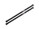 Toyota Torsion Bar
 Toyota Axle Shaft
 Toyota Bump Stop
 Toyota Control Arm Bolt
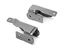 Toyota Control Arm Bracket
 Toyota Front Cross-Member
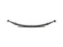 Toyota Leaf Spring
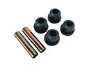 Toyota Leaf Spring Bushing
 Toyota Suspension Strut Rod
 Toyota Sway Bar Bracket
Browse Toyota Sway Bar Kit by Models
Tacoma 4Runner Camry Tundra Corolla RAV4 Highlander Prius Sienna Land Cruiser Pickup FJ Cruiser 86 Sequoia T100 Avalon Celica Supra Yaris MR2 Matrix Solara Venza GR86 Echo C-HR Cressida Grand Highlander Paseo Previa Prius C Prius Prime Corolla Cross Corolla iM Crown GR Corolla MR2 Spyder Mirai Prius V Starlet Tercel Van Yaris iA bZ4X Prius Plug-In GR Supra Prius AWD-e RAV4 Prime