×
ToyotaParts- Hello
- Login or Register
- Quick Links
- Live Chat
- Track Order
- Parts Availability
- RMA
- Help Center
- Contact Us
- Shop for
- Toyota Parts
- Scion Parts
My Garage
My Account
Cart
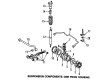
OEM Toyota Land Cruiser Sway Bar Kit
Stabilizer Sway Bar Set- Select Vehicle by Model
- Select Vehicle by VIN
Select Vehicle by Model
orMake
Model
Year
Select Vehicle by VIN
For the most accurate results, select vehicle by your VIN (Vehicle Identification Number).
15 Sway Bar Kits found


Toyota Land Cruiser Stabilizer Bar, Rear
Part Number: 48805-60060$186.74 MSRP: $266.61You Save: $79.87 (30%)
Toyota Land Cruiser Stabilizer Bar, Front
Part Number: 48811-60180$157.91 MSRP: $223.53You Save: $65.62 (30%)Ships in 1-3 Business Days
Toyota Land Cruiser Stabilizer Bar, Rear
Part Number: 48805-60110$129.83 MSRP: $183.78You Save: $53.95 (30%)Ships in 1-3 Business Days
Toyota Land Cruiser Stabilizer Bar, Front
Part Number: 48804-60120$170.95 MSRP: $242.01You Save: $71.06 (30%)Ships in 1-3 Business DaysToyota Land Cruiser Stabilizer Bar, Rear
Part Number: 48805-60090$353.20 MSRP: $517.62You Save: $164.42 (32%)Ships in 1-3 Business Days

Toyota Land Cruiser Stabilizer Bar, Rear
Part Number: 48805-60021$198.15 MSRP: $282.92You Save: $84.77 (30%)


Toyota Land Cruiser Bar, Stabilizer, Front
Part Number: 48804-60061$172.48 MSRP: $244.16You Save: $71.68 (30%)
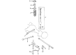
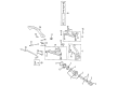
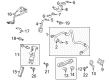
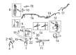
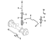
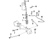
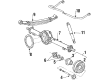
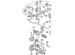
Toyota Land Cruiser Sway Bar Kit
Choose genuine Sway Bar Kit that pass strict quality control tests. You can trust the top quality and lasting durability. Shopping for OEM Sway Bar Kit for your Toyota Land Cruiser? Our website is your one-stop destination. We stock an extensive selection of genuine Toyota Land Cruiser parts. The price is affordable so you can save more. It only takes minutes to browse and find the exact fit. Easily add to cart and check out fast. Our hassle-free return policy will keep you stress-free. We process orders quickly for swift delivery. Your parts will arrive faster, so you can get back on the road sooner.
Toyota Land Cruiser Sway Bar Kit Parts and Q&A
- Q: How to install the front Sway Bar Kit on Toyota Land Cruiser?A:The installation process for the front sway bar kit begins with installing the 2 suspension control bleeder plugs to the front sway control cylinder while tightening them to 10 Nm (102 kgf-cm, 7 ft-lbf). For the installation of the front sway control cylinder to the frame use the provided bolt with washer and the nut at 275 Nm (2804 kgf-cm, 203 ft-lbf) torque. Install front No. 1 sway control tube assembly by mounting 2 new gaskets before securing it with 2 union bolts at a torque value of 69 Nm (704 kgf-cm, 51 ft-lbf). Install the exhaust center pipe assembly together with the tailpipe assembly after checking for suspension fluid leakage. Secure the sway control tube protector through two bolts by torquing them to 15 Nm (152 kgf-cm, 11 ft-lbf). The front sway control arm assembly requires one temporary installation to the front sway control cylinder through a nut and bolt combination. Install the 2 bushes onto the bush stoppers which face inside of the vehicle after bleeding air from suspension fluid. Position these bushes on the outer sides of the front sway bar bush stoppers. Set the sway bracket with its arrow mark indicating front orientation first before bolt installation of the front sway bar between 2 sway brackets along with 4 bolts. Then temporarily connect the sway bar to the sway control arm using a bolt and a nut. To install the sway link assembly on the front side of RH direction temporarily apply bolt and nut before tightening the nut to 128 Nm (1305 kgf-cm, 94 ft-lbf) using a 6 mm hexagon wrench. The stabilization of the front sway bar continues with the front sway link assembly LH requiring the stabilization control arm lift from a jack. Torque the front No. 1 sway brackets LH and RH bolts with a sequence of 87 Nm steps up to 887 kgf-cm (64 ft-lbf) using the steps provided. The technician must position the No. 1 engine under cover sub-assembly followed by the front fender splash shield sub-assemblies LH and RH. Secure the suspension before you tighten both the front sway link assembly LH bolt to 135 Nm (1377 kgf-cm, 100 ft-lbf) and its nut to 140 Nm (1428 kgf-cm, 103 ft-lbf) when all four wheels stay on the ground. When performing the bolt tightening procedure on the front sway link assembly RH maintain a torque of 135 Nm (1376 kgf-cm, 100 ft-lbf) with all 4 wheels resting on the ground. Both stabilization should be completed when all four wheels are on the ground before tightening the front sway control arm assembly nut to 190 Nm (1937 kgf-cm, 140 ft-lbf) and the front sway bar nut to 230 Nm (2345 kgf-cm, 170 ft-lbf). The technicians need to install both the front fender apron seal rear LH and front fender apron seal LH. Evaluation of suspension fluid leakage needs to be performed along with measurements of vehicle height. The sway control valve gets shuttered using the accumulator housing shutter valve then the sway control valve protector goes in and exhaust gas leak inspection completes the process.
- Q: How to remove the rear Sway Bar Kit on Toyota Land Cruiser?A:The first action for removing the rear sway bar kit starts with removal of the sway bar kit control valve protector. Start by opening the sway bar kit control with the accumulator housing shutter valve. First eject the rear wheel after taking out the tailpipe assembly and exhaust center pipe assembly. The first step requires discharging suspension fluid pressure while supporting the rear axle housing assembly. Remove the rear sway bar kit end bracket through the removal of its two bolts. Use a nut to disconnect the sway bar link assembly from the sway bar kit after which remove the rear sway bar kit sub-assembly. Maintain all ball joint dust cover protectors in place while holding the stud with a 6 mm hexagon wrench when the nut allows ball joint rotation. Taking off the 4 bolts allows removal of the sway bar kit and its accompanying bushes and brackets. The next step involves disconnecting the sway bar link sub-assembly by taking off the nut then 3 retainers along with 2 cushions followed by a nut and sway bar link with a bolt. The removal of the rear sway bar kit control tube insulator starts by unfastening two bolts. First toss the sway bar kit control tube and removed the sway bar kit control cylinder by untightening the 2 union bolts with their 2 gaskets and the bolt. After removing both nuts and bolts from the rear No. 2 sway bar link it can be removed. Take off the bolt and nut to remove the rear sway bar link assembly as the final step. Also discard the 2 rear suspension control bleeder plugs from the rear sway bar kit control cylinder.


Related Toyota Land Cruiser Parts
 Toyota Land Cruiser Alignment Bolt
 Toyota Land Cruiser Ball Joint
 Toyota Land Cruiser Bump Stop
 Toyota Land Cruiser Coil Spring Insulator
 Toyota Land Cruiser Control Arm Bushing
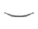 Toyota Land Cruiser Leaf Spring
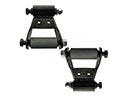 Toyota Land Cruiser Leaf Spring Shackle
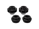 Toyota Land Cruiser Radius Arm Bushing
 Toyota Land Cruiser Shock And Strut Mount
 Toyota Land Cruiser Sway Bar Bracket
 Toyota Land Cruiser Sway Bar Link
 Toyota Land Cruiser Transfer Case Output Shaft Snap Ring