×
ToyotaParts- Hello
- Login or Register
- Quick Links
- Live Chat
- Track Order
- Parts Availability
- RMA
- Help Center
- Contact Us
- Shop for
- Toyota Parts
- Scion Parts
My Garage
My Account
Cart
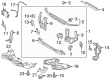
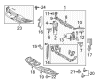
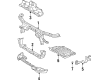
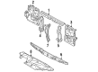
OEM Toyota Front Cross-Member
Front Engine Cross Member- Select Vehicle by Model
- Select Vehicle by VIN
Select Vehicle by Model
orMake
Model
Year
Select Vehicle by VIN
For the most accurate results, select vehicle by your VIN (Vehicle Identification Number).
286 Front Cross-Members found


Toyota Front Crossmember Part Number: 57104-47020
$561.02 MSRP: $822.18You Save: $261.16 (32%)Ships in 1 Business DayProduct Specifications- Other Name: Member Sub-Assembly, Front; Suspension Subframe Crossmember, Front; Crossmember; Member Sub-Assembly, Front Cross
- Position: Front


Toyota Lower Tie Bar, Front Part Number: 57104-06060
$136.05 MSRP: $192.60You Save: $56.55 (30%)Ships in 1-2 Business DaysProduct Specifications- Other Name: Member Sub-Assembly, Front; Radiator Support Tie Bar, Front Lower; Member Sub-Assembly, Front Cross
- Position: Front
- Replaces: 57104-33080


Toyota Engine Cradle, Front Part Number: 51201-47072
$1145.09 MSRP: $1678.14You Save: $533.05 (32%)Ships in 1-3 Business DaysProduct Specifications- Other Name: Crossmember Sub-Assembly; Suspension Subframe Crossmember, Front; Suspension Crossmember; Crossmember; Crossmember Sub-Assembly, Front Suspension
- Position: Front
- Replaces: 51201-47071, 51201-47070


Toyota Crossmember, Front Part Number: 57104-35020
$185.92 MSRP: $265.45You Save: $79.53 (30%)Ships in 1-3 Business DaysProduct Specifications- Other Name: Member Sub-Assembly, Front; Radiator Support Tie Bar, Front Lower; Member Sub-Assembly, Front Cross
- Position: Front


Toyota Front Crossmember Part Number: 57104-42070
$572.26 MSRP: $838.65You Save: $266.39 (32%)Ships in 1-3 Business DaysProduct Specifications- Other Name: Member Sub-Assembly, Front; Suspension Subframe Crossmember, Front; Member Sub-Assembly, Front Cross
- Position: Front


Toyota Front Crossmember Part Number: 57104-0R011
$567.94 MSRP: $832.33You Save: $264.39 (32%)Ships in 1-3 Business DaysProduct Specifications- Other Name: Member Sub-Assembly, Front; Suspension Subframe Crossmember, Front, Front Lower; Lower Tie Bar; Member Sub-Assembly, Front Cross
- Position: Front
- Replaces: 57104-0R010, 57104-42061


Toyota Engine Cradle, Front Part Number: 51201-02152
$868.94 MSRP: $1273.45You Save: $404.51 (32%)Ships in 1-3 Business DaysProduct Specifications- Other Name: Crossmember Sub-Assembly; Engine Cradle, Front; Crossmember; Crossmember Sub-Assembly, Front Suspension
- Position: Front
- Replaces: 51201-02090, 51201-02091, 51201-02151, 51201-02150


Toyota Suspension Crossmember, Front Part Number: 51201-52087
$931.94 MSRP: $1365.76You Save: $433.82 (32%)Ships in 1-3 Business DaysProduct Specifications- Other Name: Crossmember Sub-Assembly; Suspension Subframe Crossmember, Front; Crossmember; Crossmember Sub-Assembly, Front Suspension
- Position: Front
- Replaces: 51201-52084, 51201-52086, 51201-0D096, 51201-52083, 51201-52085, 51201-52080, 51201-0D095


Toyota Lower Tie Bar, Front Part Number: 57104-35061
$148.63 MSRP: $210.40You Save: $61.77 (30%)Ships in 1-3 Business DaysProduct Specifications- Other Name: Member Sub-Assembly, Front; Radiator Support Tie Bar, Front, Front Lower; Member Sub-Assembly, Front Cross
- Position: Front
- Replaces: 57104-35060


Toyota Lower Tie Bar, Front Part Number: 57104-04040
$176.24 MSRP: $249.49You Save: $73.25 (30%)Ships in 1 Business DayProduct Specifications- Other Name: Member Sub-Assembly, Front; Radiator Support Tie Bar, Front Lower; Member Sub-Assembly, Front Cross
- Position: Front


Toyota Lower Tie Bar, Front Part Number: 57104-07022
$317.10 MSRP: $452.75You Save: $135.65 (30%)Ships in 1-3 Business DaysProduct Specifications- Other Name: Member Sub-Assembly, Front; Radiator Support Tie Bar, Front Lower; Member Sub-Assembly, Front Cross
- Position: Front
- Replaces: 57104-07021, 57104-07020


Toyota Member Sub-Assembly, Front Cross Part Number: 57104-24021
$236.95 MSRP: $338.31You Save: $101.36 (30%)Ships in 1-3 Business DaysProduct Specifications- Other Name: Member Sub-Assembly, Front
- Position: Front


Toyota Member Sub-Assembly, Front Cross Part Number: 57104-60022
$303.35 MSRP: $433.12You Save: $129.77 (30%)Ships in 1-3 Business DaysProduct Specifications- Other Name: Member Sub-Assembly, Front
- Position: Front
- Replaces: 57104-60021, 57104-60020


Toyota Crossmember Sub-Assembly, Frame, Front Part Number: 51201-60122
$313.14 MSRP: $447.09You Save: $133.95 (30%)Ships in 1-3 Business DaysProduct Specifications- Other Name: Crossmember Sub-Assembly
- Position: Front
- Replaces: 51201-60120, 51201-60121

Toyota Engine Cradle, Front Part Number: 51100-0R012
$1551.87 MSRP: $2274.29You Save: $722.42 (32%)Ships in 1-2 Business DaysProduct Specifications- Other Name: Frame Assembly, Front; Suspension Crossmember; Crossmember; Member Sub-Assembly, Engine Front Support
- Position: Front

Toyota Engine Cradle, Front Part Number: 51100-08091
$1509.88 MSRP: $2212.74You Save: $702.86 (32%)Ships in 1-3 Business DaysProduct Specifications- Other Name: Frame Assembly; Engine Cradle, Front; Crossmember; Frame Assembly, Front
- Position: Front
- Replaces: 51100-08090

Toyota Engine Cradle Part Number: 51201-12480
$1087.77 MSRP: $1594.14You Save: $506.37 (32%)Ships in 1-2 Business DaysProduct Specifications- Other Name: Crossmember Sub-Assembly; Crossmember; Crossmember Sub-Assembly, Front Suspension

Toyota Engine Cradle Part Number: 51201-0A040
$1333.27 MSRP: $1953.93You Save: $620.66 (32%)Product Specifications- Other Name: Crossmember Sub-Assembly; Crossmember; Crossmember Sub-Assembly, Front Suspension


Toyota Crossmember, Front Part Number: 51201-35340
$712.20 MSRP: $1043.74You Save: $331.54 (32%)Product Specifications- Other Name: Crossmember Sub-Assembly; Frame Crossmember, Front; Crossmember Sub-Assembly, Frame, Front
- Position: Front


Toyota Crossmember, Front Part Number: 57104-89109
Product Specifications- Other Name: Member Sub-Assembly, Front; Member Sub-Assembly, Front Cross
- Position: Front
- Replaces: 57104-04020
| Page 1 of 15 |Next >
1-20 of 286 Results
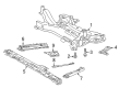
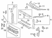
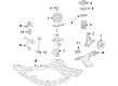
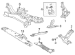
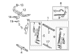
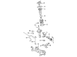
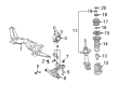
Toyota Front Cross-Member
OEM parts deliver unmatched quality you can rely on. They pass extensive quality control inspections. Toyota produces them to the official factory specifications. This process helps prevent defects and imperfections. So you can get exceptional lifespan and a flawless fit. Need new OEM Toyota Front Cross-Member? You'll love our wide selection of genuine options. Shop in minutes and skip the hunt. Our prices are unbeatable, you'll save time and money. It's easy to shop and find the right piece. Our committed customer service team gives professional help from start to finish. Every part includes a manufacturer's warranty. We ship quickly, your parts will arrive fast at your door.
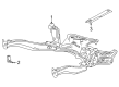
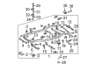
Toyota Front Cross-Member makes the chassis rigid in order to make the car stable and responsive. Toyota combines a production technique that cuts waste with instantaneous line problem solving, introduces hybrids such as the enhanced Prius plug-in and the RAV4 with 42 electric miles, and rides its TNGA platform to provide its drivers with firmer handling, enhanced safety, and trusted endurance in more international products annually. Toyota continues to innovate since 1937, with Hybrid Synergy Drive refinements that expand the low-fuel range, supporting warranty confidence with great construction quality, and gaining customer loyalty as they can definitely see their money saved at the gasoline pump, plus comfortable highway cruises and vehicles that start even when it's time to face extreme weather or other road abuse. To fit under the engine bay, Toyota attaches the Front Cross-Member, a model boxed profile made of steel which prevents twisting, aligns the suspension pick-up points, and keeps the drivetrain straight so when steering the vehicle in the corners, the body moves smoothly across bumps and the braking under panic. Toyota designs the Front Cross-Member to match longitudinal engine layouts and provides torsional stiffness to maintain the same level of camber, tires to stick to the road during lane changes and powertrains to lack excessive weight, which in turn translates to a faster response, less vibration through the cabin, and strong ability. The Front Cross-Member can withstand rough daily roads.
Toyota Front Cross-Member Parts and Q&A
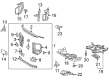
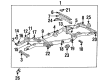
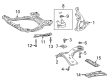
- Q: How to install the Front Cross-Member on Toyota Highlander?A:Install the front suspension member by first placing the new front suspension member body mounting rear cushion LH in the correct direction and then use Special Service Tool: 09830-10010 to fasten it while verifying no space remains between the front suspension member and the cushion. Apply the same procedure to the front suspension member body mounting rear cushion RH through the use of Special Service Tool: 09830-10010. To secure the new front suspension member body mounting front cushion temporarily you need to check its installation direction and clamp it with Special Service Tool: 09830-10010 and confirm it is free of clearance space. The technician should install front suspension member body mounting rear stopper and front stopper before installing the front suspension member dynamic damper with two bolts torqued to 29 Nm (296 kgf-cm, 21 ft-lbf). Install both the front lower suspension arm LH then install its counterpart on the RH side through the same installation process. The next step involves installation of the transverse engine mounting insulator along with front frame assembly before the engine hangers can be removed. The installation process starts with the power steering link assembly and proceeds to front stabilizer bar installation in combination with the front stabilizer link assembly. The same steps apply to both sides as technicians install No. 1 front stabilizer bracket LH and No. 1 front stabilizer bracket RH. The last step of installation includes placing the engine assembly with its transaxle.
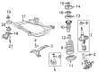
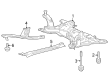
- Q: How to install the Front Cross-Member and associated components on Toyota Venza?A:The installation of the front suspension member starts with fitting the new front suspension member body mounting rear cushion LH in its proper direction while using Special Service Tool: 09830-10010 for attachment then verifying the front suspension member does not overlap the cushion. Do this also for the front suspension member body mounting rear cushion RH. For installing the rear cushion RH of the front suspension member body mounting use the exact tool to follow the same procedure. Put the front suspension member body mounting front cushion into position with appropriate orientation before tightening it using Special Service Tool: 09830-10010 and verifying clearance between the components. First install the two front suspension member body mounting rear stopper and front stopper pieces and then place the front suspension member dynamic damper for 2WD using two bolts with a torque setting of 29 Nm (296 kgf-cm, 21 ft-lbf). For both sides install the front lower suspension arms beginning with the LH then proceeding to the RH while following the exact installation procedure. The front engine mounting insulator assembly together with its components including the 2GR-FE's engine mounting insulators LH and RH and rear engine mounting insulator need to be first torqued temporarily before installing the front frame assembly. The 2GR-FE engine mounting insulators must be fully tightened after performing temporary and full tightening steps for the 1AR-FE and 1AR-FE AWD configurations. To finish engine assembly with transaxle installation for the 2GR-FE and 1AR-FE, you should install steering link assembly, front stabilizer bar with front stabilizer link assembly and front No. 1 stabilizer brackets LH and RH.


Related Toyota Parts
 Toyota Sway Bar Link
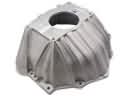 Toyota Bellhousing
 Toyota Coil Springs
 Toyota Torsion Bar
 Toyota Coil Spring Insulator
 Toyota Differential Mount
 Toyota Lateral Link
 Toyota Rear Crossmember
 Toyota Shock Absorber
 Toyota Sway Bars
 Toyota Transfer Case Output Shaft Snap Ring
 Toyota Wheel Seal
Browse Toyota Front Cross-Member by Models
Tacoma 4Runner Camry Tundra Corolla RAV4 Highlander Prius Sienna Land Cruiser Pickup FJ Cruiser 86 Sequoia T100 Avalon Celica Supra Yaris Matrix MR2 Solara Venza GR86 Echo C-HR Cressida Grand Highlander Paseo Previa Prius C Prius Prime bZ4X Corolla Cross Corolla iM Crown Crown Signia GR Corolla Mirai MR2 Spyder Prius V Starlet Tercel Van Yaris iA Prius Plug-In GR Supra Prius AWD-e RAV4 Prime