×
ToyotaParts- Hello
- Login or Register
- Quick Links
- Live Chat
- Track Order
- Parts Availability
- RMA
- Help Center
- Contact Us
- Shop for
- Toyota Parts
- Scion Parts
My Garage
My Account
Cart
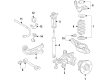
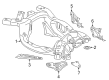
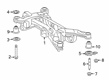
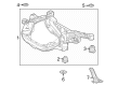
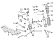
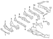
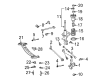
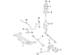
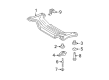
OEM Toyota Rear Crossmember
Rear Suspension Crossmember- Select Vehicle by Model
- Select Vehicle by VIN
Select Vehicle by Model
orMake
Model
Year
Select Vehicle by VIN
For the most accurate results, select vehicle by your VIN (Vehicle Identification Number).
110 Rear Crossmembers found


Toyota Suspension Crossmember, Rear Part Number: 51270-0C012
$1217.96 MSRP: $1784.93You Save: $566.97 (32%)Ships in 1-3 Business DaysProduct Specifications- Other Name: Member Assembly, Rear Suspension; Suspension Subframe Crossmember, Rear; Member Sub-Assembly, Rear Suspension
- Position: Rear
- Replaces: 51270-0C010


Toyota Suspension Crossmember, Rear Part Number: 51206-20130
$369.43 MSRP: $541.41You Save: $171.98 (32%)Ships in 1-3 Business DaysProduct Specifications- Other Name: Member Sub-Assembly, Rear; Suspension Subframe Crossmember, Rear
- Position: Rear
- Replaces: 51206-20100


Toyota Member Sub-Assembly, Rear Suspension Part Number: 51206-33040
$503.93 MSRP: $738.51You Save: $234.58 (32%)Ships in 1-3 Business DaysProduct Specifications- Other Name: Member Sub-Assembly, Rear
- Position: Rear
- Replaces: 51206-06040, 51206-33020, 51206-33021, 51206-06041, 51206-33022, 51206-06042, 51206-06033


Toyota Crossmember, Rear Part Number: 51290-60010
$641.15 MSRP: $939.61You Save: $298.46 (32%)Ships in 1-3 Business DaysProduct Specifications- Other Name: Crossmember Assembly, Front; Frame Crossmember, Rear; Crossmember, Frame, Rear
- Position: Rear

Toyota Suspension Crossmember, Rear Part Number: 51206-02060
$1009.34 MSRP: $1479.21You Save: $469.87 (32%)Ships in 1-3 Business DaysProduct Specifications- Other Name: Member Sub-Assembly, Rear; Suspension Subframe Crossmember, Rear; Crossmember; Member Sub-Assembly, Rear Suspension
- Position: Rear

Toyota Member Sub-Assembly, Rear Suspension Part Number: 51206-48060
$1089.02 MSRP: $1595.97You Save: $506.95 (32%)Ships in 1-3 Business DaysProduct Specifications- Other Name: Member Sub-Assembly, Rear
- Position: Rear

Toyota Suspension Crossmember, Rear Part Number: 51200-0R010
$1527.13 MSRP: $2238.03You Save: $710.90 (32%)Ships in 1-3 Business DaysProduct Specifications- Other Name: Frame Assembly, Rear; Suspension Subframe Crossmember, Rear; Crossmember; Member Sub-Assembly, Rear Suspension
- Position: Rear

Toyota Suspension Crossmember, Rear Part Number: 51200-42040
$1414.88 MSRP: $2073.53You Save: $658.65 (32%)Ships in 1-3 Business DaysProduct Specifications- Other Name: Frame Assembly, Rear; Member Sub-Assembly, Rear Suspension
- Position: Rear

Toyota Member Sub-Assembly, Center Floor Panel Part Number: 57405-30100
$415.74 MSRP: $609.27You Save: $193.53 (32%)Ships in 1-2 Business DaysProduct Specifications- Other Name: MEMBER SUB-ASSY, CTR
- Position: Center

Toyota Rear Crossmember Part Number: 51209-0C013
$420.62 MSRP: $616.42You Save: $195.80 (32%)Ships in 1-3 Business DaysProduct Specifications- Other Name: Crossmember Sub-Assembly
- Replaces: 51209-0C010, 51209-0C012

Toyota Suspension Crossmember, Rear Part Number: 51206-0E014
$465.57 MSRP: $682.29You Save: $216.72 (32%)Product Specifications- Other Name: Member Sub-Assembly, Rear; Suspension Subframe Crossmember, Rear; Crossmember; Member Sub-Assembly, Rear Suspension
- Position: Rear
- Replaces: 51206-48031, 51206-0E013, 51206-0E011, 51206-48032, 51206-48030, 51206-48070, 51206-0E012, 51206-48071

Toyota Suspension Crossmember, Rear Part Number: SU003-10927
$518.56 MSRP: $759.96You Save: $241.40 (32%)Ships in 1-3 Business DaysProduct Specifications- Other Name: Sub Frame Assembly Rear Suspension; Suspension Subframe Crossmember, Rear; Crossmember
- Position: Rear
- Replaces: SU003-00349

Toyota Suspension Crossmember, Rear Part Number: 51206-17030
$525.97 MSRP: $770.81You Save: $244.84 (32%)Ships in 1-3 Business DaysProduct Specifications- Other Name: Member Sub-Assembly, Rear; Suspension Subframe Crossmember, Rear; Member Sub-Assembly, Rear Suspension
- Position: Rear

Toyota Front Crossmember Part Number: 51202-0C050
$584.85 MSRP: $857.11You Save: $272.26 (32%)Ships in 1-3 Business DaysProduct Specifications- Other Name: Crossmember Sub-Assembly; Frame Crossmember, Front; Crossmember; Crossmember Sub-Assembly, Frame
- Position: Front
Toyota Suspension Crossmember, Rear Part Number: 51206-17040
$590.64 MSRP: $865.59You Save: $274.95 (32%)Ships in 1-3 Business DaysProduct Specifications- Other Name: Member Sub-Assembly, Rear; Suspension Subframe Crossmember, Rear; Member Sub-Assembly, Rear Suspension
- Position: Rear

Toyota Suspension Crossmember, Rear Part Number: 51206-33100
$651.14 MSRP: $954.25You Save: $303.11 (32%)Ships in 1-3 Business DaysProduct Specifications- Other Name: Member Sub-Assembly, Rear; Suspension Subframe Crossmember, Rear; Member Sub-Assembly, Rear Suspension
- Position: Rear
- Replaces: 51206-33060, 51206-33061

Toyota Suspension Crossmember, Rear Part Number: 51206-0E015
$686.66 MSRP: $1006.31You Save: $319.65 (32%)Ships in 1-3 Business DaysProduct Specifications- Other Name: Member Sub-Assembly, Rear; Suspension Subframe Crossmember, Rear; Crossmember; Member Sub-Assembly, Rear Suspension
- Position: Rear

Toyota Suspension Crossmember, Rear Part Number: 51206-06104
$686.66 MSRP: $1006.31You Save: $319.65 (32%)Ships in 1-3 Business DaysProduct Specifications- Other Name: Member Sub-Assembly, Rear; Suspension Subframe Crossmember, Rear; Member Sub-Assembly, Rear Suspension
- Position: Rear
Toyota Suspension Crossmember, Rear Part Number: 51206-06103
$689.05 MSRP: $1009.81You Save: $320.76 (32%)Ships in 1-3 Business DaysProduct Specifications- Other Name: Member Sub-Assembly, Rear; Suspension Subframe Crossmember, Rear; Crossmember; Member Sub-Assembly, Rear Suspension
- Position: Rear
- Replaces: 51206-06100, 51206-0E030, 51206-06102, 51206-06051, 51206-06101, 51206-06050


Toyota Rear Crossmember Part Number: 51209-60111
$696.65 MSRP: $1020.96You Save: $324.31 (32%)Product Specifications- Other Name: Crossmember Sub-Assembly; Reinforcement; Crossmember; Crossmember, Frame, Rear
- Position: Rear
| Page 1 of 6 |Next >
1-20 of 110 Results
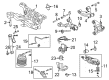
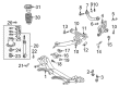
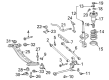
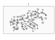
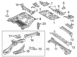
Toyota Rear Crossmember
OEM parts deliver unmatched quality you can rely on. They pass extensive quality control inspections. Toyota produces them to the official factory specifications. This process helps prevent defects and imperfections. So you can get exceptional lifespan and a flawless fit. Need new OEM Toyota Rear Crossmember? You'll love our wide selection of genuine options. Shop in minutes and skip the hunt. Our prices are unbeatable, you'll save time and money. It's easy to shop and find the right piece. Our committed customer service team gives professional help from start to finish. Every part includes a manufacturer's warranty. We ship quickly, your parts will arrive fast at your door.
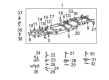
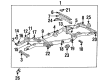
Toyota Rear Crossmember is what stiffens the backbone of the vehicle to prevent frame twisting and maintain drive train alignment. What started as a small factory in 1937 Japan, Toyota became a worldwide manufacturer that values the absence of wastage during the production process and the quick solution of problems. Hybrids are fast rolling and the recent plug-in systems squeeze several miles out of each drop and reduce tailpipe clouds. Drivers have faith in the badge due to the fact that cars created on the flexible TNGA platform are more precise in steering, comfortable to ride, and put up with everyday abuse. New entries such as the RAV4 plug-in indicate that the brand is uniting the electric range with commanding acceleration without sacrificing either end. Long life is better than flash and thus corrosion-resistant metals and intelligent packaging will make odometers rotate beyond the competition. Toyota continues to hone these fundamentals which demonstrate permanence can coexist with changing technology. Rear Crossmember slots beneath the frame rails create a stiff bridge that supports engine and transmission loads across uneven surfaces. Suspension links are also anchored by Rear Crossmember; therefore, they do not bend when potholes strike severely. Rear Crossmember is made with new steel alloys and rust-resistant finishes, reducing weight and increasing service in salty environments. Toyota uses the same Rear Crossmember blueprint generation to year, allowing a part to fit many models with no additional adjustments. This cross frame brace withstands bending, gives the cabin vibrations at low levels, and tow ratings truthful.
Toyota Rear Crossmember Parts and Q&A
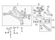
- Q: How to install the Rear Crossmember on Toyota Highlander?A:Install first the stud bolts to both LH and RH sides of the 2WD rear suspension member before torquing them to 17 Nm (173 kgf-cm, 12 ft-lbf). Both sizes of hole plugs need installation into the rear suspension member sub-assembly. Utilize Special Service Tool: 09950-70010 09951-07100 along with a press to fully install the rear suspension member body mounting front cushion LH after installing it temporarily while making sure the cushion fits snugly with the sub-assembly without any space present while also avoiding damage to the member. Perform this procedure once again for the RH side cushion. Install each rear cushion according to the same procedure for left-hand and right-hand sides while avoiding excessive installation pressure. Use the jack and wooden blocks to lift the rear suspension member before fastening it with 4 nuts according to bolt torque specifications while installing the stoppers using 2 bolts torqued to 55 Nm (561 kgf-cm, 40 ft-lbf). Sub-assemble the exhaust pipe clamp bracket with three bolts while connecting the exhaust pipe clamp. The rear suspension arm assemblies of both LH and RH sides should be temporarily installed while stabilizing the suspension before a complete tightening procedure is performed on all arm assemblies. The installation order requires rear stabilizer bar and link assembly placement on both sides before torquing the rear wheels to 103 Nm (1,050 kgf-cm, 76 ft-lbf). The last installation steps require placing the spare wheel carrier lock cover followed by setting up the spare tire then finishing with the lower spare wheel carrier hinge cover and deck trim service hole cover and rear mat and tonneau cover assembly and No. 2 and No. 3 deck board sub-assemblies and deck board assembly followed by checking and correcting the rear wheel alignment.
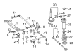
- Q: What is the function of the rear crossmember in the rear suspension system on Toyota Matrix?A:The rear suspension depends heavily on the rear cross-member to work properly because this part provides vital support to the vehicle's structure. To achieve good handling and stability you need to take care of the rear cross-member during service and fixes. Scheduled checks and servicing help discover and address parts of the rear suspension system that suffer damage.


Related Toyota Parts
 Toyota Control Arm
 Toyota Axle Shaft
 Toyota Coil Spring Insulator
 Toyota Control Arm Bracket
 Toyota Crossmember Bushing
 Toyota Lateral Link
 Toyota Radius Arm Bushing
 Toyota Shock Absorber
 Toyota Sway Bar Bracket
 Toyota Sway Bar Bushing
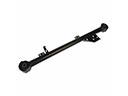 Toyota Trailing Arm
 Toyota Transfer Case Output Shaft Snap Ring