×
ToyotaParts- Hello
- Login or Register
- Quick Links
- Live Chat
- Track Order
- Parts Availability
- RMA
- Help Center
- Contact Us
- Shop for
- Toyota Parts
- Scion Parts
My Garage
My Account
Cart
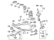
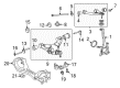
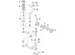
OEM Toyota Control Arm
Suspension Arm- Select Vehicle by Model
- Select Vehicle by VIN
Select Vehicle by Model
orMake
Model
Year
Select Vehicle by VIN
For the most accurate results, select vehicle by your VIN (Vehicle Identification Number).
373 Control Arms found


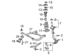
Toyota Control Arm, Lower Driver Side Part Number: 48069-08040
$159.20 MSRP: $225.37You Save: $66.17 (30%)Ships in 1-3 Business DaysProduct Specifications- Other Name: Arm Sub-Assembly, Suspension; Suspension Control Arm, Front Left; Control Arm Assembly; Lower Control Arm; Arm Sub-Assembly, Front Suspension, Lower Driver Side
- Position: Lower Driver Side

Toyota Control Arm, Passenger Side Part Number: 48068-08040
$159.20 MSRP: $225.37You Save: $66.17 (30%)Ships in 1-3 Business DaysProduct Specifications- Other Name: Arm Sub-Assembly, Suspension; Suspension Control Arm, Front Right; Control Arm Assembly; Lower Control Arm; Arm Sub-Assembly, Front Suspension, Lower Passenger Side
- Position: Passenger Side


Toyota Arm Sub-Assembly, Front Suspension, Lower Driver Side Part Number: 48069-0E050
$159.79 MSRP: $226.20You Save: $66.41 (30%)Ships in 1-2 Business DaysProduct Specifications- Other Name: Arm Sub-Assembly, Suspension; Control Arm
- Position: Lower Driver Side
- Replaces: 48069-0T011, 48069-48070, 48069-48041, 48069-0T010, 48069-48040


Toyota Control Arm, Passenger Side Part Number: 48068-0E050
$159.79 MSRP: $226.20You Save: $66.41 (30%)Ships in 1-2 Business DaysProduct Specifications- Other Name: Arm Sub-Assembly, Suspension; Suspension Control Arm, Front Right; Control Arm Assembly; Lower Control Arm; Arm Sub-Assembly, Front Suspension, Lower Passenger Side
- Position: Passenger Side
- Replaces: 48068-48040, 48068-0T010, 48068-0T011, 48068-48041, 48068-48070


Toyota Upper Control Arm, Passenger Side Part Number: 48610-60060
$301.84 MSRP: $430.96You Save: $129.12 (30%)Ships in 1-3 Business DaysProduct Specifications- Other Name: Arm Assembly, Suspension; Suspension Control Arm, Front Right Upper; Control Arm Assembly; Arm Assembly, Front Suspension Upper, Passenger Side; Control Arm
- Position: Passenger Side


Toyota Lower Control Arm, Passenger Side Part Number: 48068-04060
$278.07 MSRP: $397.03You Save: $118.96 (30%)Product Specifications- Other Name: Arm Sub-Assembly, Suspension; Suspension Control Arm, Front Right Lower; Control Arm Assembly; Arm Sub-Assembly, Front Suspension, Lower Passenger Side; Control Arm
- Position: Passenger Side


Toyota Lower Control Arm, Passenger Side Part Number: 48068-34020
$232.56 MSRP: $332.04You Save: $99.48 (30%)Ships in 1-2 Business DaysProduct Specifications- Other Name: Arm Sub-Assembly, Suspension; Suspension Control Arm, Front Right Lower; Arm Sub-Assembly, Front Suspension, Lower Passenger Side; Suspension Control Arm; Control Arm
- Position: Passenger Side
- Replaces: 48068-34030

Toyota Lower Control Arm, Driver Side Part Number: 48069-04060
$271.08 MSRP: $387.04You Save: $115.96 (30%)Product Specifications- Other Name: Arm Sub-Assembly, Suspension; Suspension Control Arm, Front Left Lower; Control Arm Assembly; Arm Sub-Assembly, Front Suspension, Lower Driver Side; Control Arm
- Position: Lower Driver Side


Toyota Lower Control Arm, Passenger Side Part Number: 48620-60010
$322.51 MSRP: $460.47You Save: $137.96 (30%)Ships in 1-3 Business DaysProduct Specifications- Other Name: Arm Assembly, Suspension; Suspension Control Arm, Front Right Lower; Control Arm Assembly; Arm Assembly, Front Suspension, Lower Passenger Side; Suspension Control Arm; Control Arm
- Position: Lower Passenger Side


Toyota Lower Control Arm, Driver Side Part Number: 48069-02310
$159.20 MSRP: $225.37You Save: $66.17 (30%)Ships in 1-3 Business DaysProduct Specifications- Other Name: Arm Sub-Assembly, Suspension; Suspension Control Arm, Front Left; Control Arm Assembly; Arm Sub-Assembly, Front Suspension, Lower Driver Side; Control Arm
- Position: Lower Driver Side
- Replaces: 48069-47060


Toyota Control Arm, Lower Driver Side Part Number: 48069-02190
$173.54 MSRP: $245.66You Save: $72.12 (30%)Ships in 1 Business DayProduct Specifications- Other Name: Arm Sub-Assembly, Suspension; Suspension Control Arm, Front Left; Control Arm Assembly; Lower Control Arm; Arm Sub-Assembly, Front Suspension, Lower Driver Side; Suspension Control Arm
- Position: Lower Driver Side

Toyota Control Arm, Passenger Side Part Number: 48068-02190
$173.54 MSRP: $245.66You Save: $72.12 (30%)Ships in 1-3 Business DaysProduct Specifications- Other Name: Arm Sub-Assembly, Suspension; Suspension Control Arm, Front Right; Control Arm Assembly; Lower Control Arm; Arm Sub-Assembly, Front Suspension, Lower Passenger Side; Suspension Control Arm
- Position: Passenger Side


Toyota Upper Control Arm, Driver Side Part Number: 48630-34010
$225.42 MSRP: $321.84You Save: $96.42 (30%)Ships in 1-2 Business DaysProduct Specifications- Other Name: Arm Assembly, Suspension; Suspension Control Arm, Front Left Upper; Arm Assembly, Front Suspension, Upper Driver Side; Suspension Control Arm; Control Arm
- Position: Upper Driver Side

Toyota Upper Control Arm, Passenger Side Part Number: 48610-34010
$245.80 MSRP: $350.95You Save: $105.15 (30%)Ships in 1-2 Business DaysProduct Specifications- Other Name: Arm Assembly, Suspension; Suspension Control Arm, Front Right Upper; Arm Assembly, Front Suspension Upper, Passenger Side; Suspension Control Arm; Control Arm
- Position: Passenger Side


Toyota Control Arm, Passenger Side Part Number: 48068-0R030
$191.40 MSRP: $273.27You Save: $81.87 (30%)Ships in 1-3 Business DaysProduct Specifications- Other Name: Arm Sub-Assembly, Suspension; Suspension Control Arm, Front Right; Control Arm Assembly; Lower Control Arm; Arm Sub-Assembly, Front Suspension, Lower Passenger Side; Suspension Control Arm
- Position: Passenger Side
- Replaces: 48068-42060


Toyota Lower Control Arm, Passenger Side Part Number: 48068-04040
$283.88 MSRP: $405.30You Save: $121.42 (30%)Product Specifications- Other Name: Arm Sub-Assembly, Suspension; Suspension Control Arm, Front Right Lower; Control Arm Assembly; Arm Sub-Assembly, Front Suspension, Lower Passenger Side; Control Arm
- Position: Passenger Side


Toyota Upper Control Arm, Passenger Side Part Number: 48610-60030
$354.34 MSRP: $519.28You Save: $164.94 (32%)Ships in 1-3 Business DaysProduct Specifications- Other Name: Arm Assembly, Suspension; Suspension Control Arm, Front Right Upper; Control Arm Assembly; Arm Assembly, Front Suspension Upper, Passenger Side; Suspension Control Arm; Control Arm
- Position: Passenger Side


Toyota Control Arm, Lower Driver Side Part Number: 48069-07040
$166.13 MSRP: $235.18You Save: $69.05 (30%)Ships in 1-3 Business DaysProduct Specifications- Other Name: Arm Sub-Assembly, Suspension; Suspension Control Arm, Front Left; Control Arm Assembly; Lower Control Arm; Arm Sub-Assembly, Front Suspension, Lower Driver Side
- Position: Lower Driver Side


Toyota Lower Control Arm, Passenger Side Part Number: 48068-0E060
$159.79 MSRP: $226.20You Save: $66.41 (30%)Ships in 1-3 Business DaysProduct Specifications- Other Name: Arm Sub-Assembly, Suspension; Suspension Control Arm, Front Right; Control Arm Assembly; Arm Sub-Assembly, Front Suspension, Lower Passenger Side; Control Arm
- Position: Passenger Side


Toyota Control Arm, Passenger Side Part Number: 48068-07040
$175.32 MSRP: $250.32You Save: $75.00 (30%)Ships in 1-3 Business DaysProduct Specifications- Other Name: Arm Sub-Assembly, Suspension; Suspension Control Arm, Front Right; Control Arm Assembly; Lower Control Arm; Arm Sub-Assembly, Front Suspension, Lower Passenger Side
- Position: Passenger Side
| Page 1 of 19 |Next >
1-20 of 373 Results
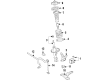
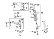
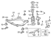
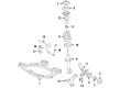
Toyota Control Arm
OEM parts deliver unmatched quality you can rely on. They pass extensive quality control inspections. Toyota produces them to the official factory specifications. This process helps prevent defects and imperfections. So you can get exceptional lifespan and a flawless fit. Need new OEM Toyota Control Arm? You'll love our wide selection of genuine options. Shop in minutes and skip the hunt. Our prices are unbeatable, you'll save time and money. It's easy to shop and find the right piece. Our committed customer service team gives professional help from start to finish. Every part includes a manufacturer's warranty. We ship quickly, your parts will arrive fast at your door.
Toyota Control Arm ensures that the wheel is in line and also the suspension follows the bumps without any drama. Toyota is a company that thrives on lean production that reduces wastage, enables line workers to intercept defects early and pours savings into research that is eventually experienced by ordinary drivers on the road. With its modular TNGA platform, which is a ubiquitous backbone shared among compacts and SUVs, simplifies assembly, lowers the cost, reduces the mass, decreases the center of gravity, and sharpens the turn-in without affecting ride comfort, Toyota raised the bar. Whether it is raining or not, cornering is flatter and braking is straight. Toyota now tripled the hybrids, introducing better batteries, more powerful electric motors, and a Prius platform now overflowing into virtually any body style showing that efficiency could be paired with roughness at least as far as the hour hand. When there is reduced fuel consumed, it means that there are increased funds to use in road trips. The second Control Arm can also be known as a wishbone and is connected to the wheel hub via a unibody pivot that allows the tire to swing in a clean vertical arc. Stamped steel is applied in daily driving and cast aluminum resists corrosion and casts its weight, which furnishes the Control Arm with a higher endurance when potholes hit at high speed. The payoff is experienced by the drivers as a steady Control Arm sustains the camber and toe, prevents the shimmy, and maintains the steering feedback sharp on torn pavement. Worn out bushings or ball joints will make a fresh Control Arm purchase calm, and the owners of Toyota can upgrade their power options to have better high-speed control.
Toyota Control Arm Parts and Q&A
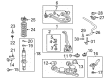
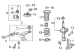
- Q: How to remove and install the upper control arm on 2003 through 2009 Toyota 4Runner?A:Loosen the wheel lug nuts, raise the front of the vehicle, and support it securely on jackstands while applying the parking brake before removing the wheel. Disconnect the wheel speed sensor wiring harness and separate it from the upper control arm and steering knuckle. For clearance to remove the upper arm pivot bolt, take off the wire harness bracket, which is mounted where the bracket meets the body. Support the lower control arm with a floor jack, then remove the retaining clip and loosen the upper balljoint nut about 1/4 inch. Use a two-jaw puller or a balljoint separator to detach the balljoint from the steering knuckle, ensuring the steering knuckle does not fall outward to avoid damaging the brake hose; tying it to the coil spring can help prevent this. Remove the nut, washer, and pivot bolt to detach the upper control arm from the frame, being cautious not to damage the splash shields on each side of the control arm, which can be removed by prying out the fasteners if necessary. Inspect the bushings for wear and deterioration, and if they are cracked or damaged, take the arm to an automotive machine shop for new bushings. Installation follows the reverse order of removal, ensuring all suspension fasteners are tightened to the specified torque and using a new retaining clip on the upper control arm balljoint nut. If needed, tighten the balljoint nut further to align the hole in the ballstud with the slots in the nut without loosening it. The pivot bolt nut should be tightened with the vehicle at normal ride height, which can be achieved after lowering the vehicle or by raising the lower control arm with a floor jack. Finally, tighten the lug nuts to the specified torque and consider having the wheel alignment checked and adjusted if necessary.
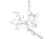
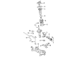
- Q: How to remove and install a rear lower control arm on Toyota Sequoia?A:Always support the lower control arm before removing the lower shack mounting bolts, because the lower control arm will drop about 3 inches. Inspect the bushings for wear and deterioration. If they're cracked or damaged, take the arm to an automotive machine shop and have new bushings installed. Loosen the rear wheel lug nuts, raise the rear of the vehicle and support it securely on jackstands. Block the front wheels to keep the vehicle from rolling off the stands. Remove the wheel. Remove the rear shock absorber. Make alignment marks on the front and outer adjusting cams. Hold the adjusting cam plate nuts with a wrench and unscrew the pivot bolts and rear bolt. Remove all the bolts and detach the lower control arm from the frame. Installation is the reverse of removal. Make sure that the alignment marks you made prior to disassembly are lined up. Tighten all suspension fasteners. The pivot bolts should be tightened with the vehicle at normal ride height. This can be done after the vehicle has been lowered to the ground (on vehicles with adequate clearance), or can be simulated by raising the lower control arm with a floor jack. Remove the rear coil spring or air bag. If equipped remove the rear air bags assembly. Remove the cotter pin, then loosen the lower balljoint nut a few turns. Using a two-jaw puller or a pickle fork-type balljoint separator, separate the balljoint from the lower control arm. Make alignment marks on the adjusting cams. Hold the adjusting cam plate nut with a wrench and unscrew the bolt. Remove all the bolt and detach the lower control arm from the frame. Installation is the reverse of removal. Make sure that the alignment marks you made prior to disassembly are lined up. Tighten all suspension fasteners. The pivot bolts should be tightened with the vehicle at normal ride height. This can be done after the vehicle has been lowered to the ground (on vehicles with adequate clearance), or can be simulated by raising the lower control arm with a floor jack.


Related Toyota Parts
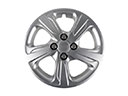 Toyota Wheel Cover
 Toyota Ball Joint
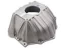 Toyota Bellhousing
 Toyota CV Boot
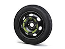 Toyota Spare Wheel
 Toyota Bump Stop
 Toyota Front Cross-Member
 Toyota Lateral Link
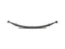 Toyota Leaf Spring
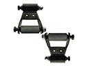 Toyota Leaf Spring Shackle
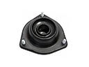 Toyota Strut Mounts
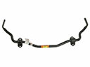 Toyota Sway Bars
Browse Toyota Control Arm by Models
Tacoma 4Runner Camry Tundra Corolla RAV4 Highlander Prius Sienna Land Cruiser Pickup FJ Cruiser 86 Sequoia T100 Avalon Celica Supra Yaris Matrix MR2 Solara Venza GR86 Echo C-HR Cressida Grand Highlander Paseo Previa Prius C Prius Prime bZ4X Corolla Cross Corolla iM Crown Crown Signia GR Corolla Mirai MR2 Spyder Prius V Starlet Tercel Van Yaris iA Prius Plug-In GR Supra Prius AWD-e RAV4 Prime