×
ToyotaParts- Hello
- Login or Register
- Quick Links
- Live Chat
- Track Order
- Parts Availability
- RMA
- Help Center
- Contact Us
- Shop for
- Toyota Parts
- Scion Parts
My Garage
My Account
Cart
OEM Toyota Celica Control Arm
Suspension Arm- Select Vehicle by Model
- Select Vehicle by VIN
Select Vehicle by Model
orMake
Model
Year
Select Vehicle by VIN
For the most accurate results, select vehicle by your VIN (Vehicle Identification Number).
22 Control Arms found

Toyota Celica Lower Control Arm, Rear Driver Side Part Number: 48720-20090
$162.57 MSRP: $230.15You Save: $67.58 (30%)Ships in 1-3 Business Days

Toyota Celica Control Arm, Lower Driver Side Part Number: 48069-20290


Toyota Celica Control Arm, Passenger Side Part Number: 48068-20290
Toyota Celica Lower Control Arm, Passenger Side Part Number: 48068-20381
$214.93 MSRP: $306.87You Save: $91.94 (30%)
Toyota Celica Control Arm, Lower Driver Side Part Number: 48069-29065

Toyota Celica Control Arm, Passenger Side Part Number: 48068-29065

Toyota Celica Control Arm, Lower Driver Side Part Number: 48069-20160

Toyota Celica Control Arm, Passenger Side Part Number: 48068-20160

Toyota Celica Control Arm, Lower Driver Side Part Number: 48069-20250

Toyota Celica Control Arm, Passenger Side Part Number: 48068-20210
Toyota Celica Control Arm, Passenger Side Part Number: 48068-20250
Toyota Celica Lower Control Arm, Driver Side Part Number: 48069-20381
Toyota Celica Control Arm, Lower Driver Side Part Number: 48069-20210
Toyota Celica Control Arm, Passenger Side Part Number: 48068-29125
Toyota Celica Lower Control Arm, Driver Side Part Number: 48069-20370
Toyota Celica Control Arm, Driver Side Part Number: 48069-29125

Toyota Celica Control Arm, Rear Part Number: 48703-22923
| Page 1 of 2 |Next >
1-20 of 22 Results
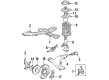
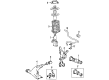
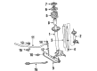
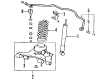
Toyota Celica Control Arm
Choose genuine Control Arm that pass strict quality control tests. You can trust the top quality and lasting durability. Shopping for OEM Control Arm for your Toyota Celica? Our website is your one-stop destination. We stock an extensive selection of genuine Toyota Celica parts. The price is affordable so you can save more. It only takes minutes to browse and find the exact fit. Easily add to cart and check out fast. Our hassle-free return policy will keep you stress-free. We process orders quickly for swift delivery. Your parts will arrive faster, so you can get back on the road sooner.
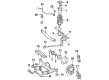
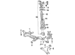
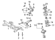
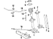
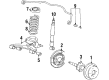
Control Arm Toyota Celica automobiles are quite important because they link the frame with the wheels and hold essential suspension equipment such as shocks and springs. These arms swivel according to the status of roads and facilitate movement of wheels in the up and down position. Although there are many kinds of control arms utilized in combinations with other suspension types, all control arms always possess bushings at the area through which they are fastened to the frame and ball joints at the part at which they are linked to the knuckle or axle. Succeeding models of Celica may have control arms that are made of cast iron or aluminum to enhance the sturdiness and endurance. These are core components required for correct geometric alignment, handling balance, and long tread wear on the tires, particularly after raising or lowering the vehicle's suspension and cornering at high speed.
Toyota Celica Control Arm Parts and Q&A
- Q: How to remove the front control arm on Toyota Celica?A:The front control arm removal process starts by first removing the wheel and using torque at 103 Nm (1,050 kgf.cm, 76 ft.lbs.). The first step is to take off the engine under cover followed by a lower suspension arm detachment at the lower Ball Joint through bolt and nut removal while using 142 Nm of torque (1,450 kgf.cm, 105 ft. lbs.). To replace the lower suspension arm and its nut as well as two bolts you must follow the sequence of steps. First, tighten the suspension bolts with 137 Nm torque while the suspension remains stable during installation. When working on the A/T LH side you will need to remove engine under covers while disconnecting the RH and LH tie rod ends through nut removal and cotter pin removal at 49 Nm (500 kgf.cm, 36 ft. lbs.) torque until reaching 60° when the cotter pin holes are not aligned properly. Use Special Service Tool: 09610-20012 to detach the steering knuckle tie rod end before moving onto the other side. The procedure starts with disconnecting the stabilizer bar links by removing the nut and removing the stabilizer bar link from the Shock Absorber with a torque of 44 Nm (449 kgf.cm, 32 ft. lbs.). A hexagon (5 mm) wrench should be used to hold the stud in case the ball joint turns with the nut. The procedure ends with disconnected RH and LH lower suspension arms from their lower ball joints after removing bolt and 2 nuts tightened to 142 Nm (1,450 kgf.cm, 105 ft. lbs.). Correctly torque the lower suspension arm set bolts to 137 Nm while the vehicle suspension remains stable to the point where you should torque these bolts after final suspension adjustments. The engine hood removal will allow attachment of the engine sling device to the hangers while the disconnect process of 2 PCV hoses requires proper engagement of the No. 1 and No. 2 hangers in correct orientation using part numbers 12281-22021 and 12281-15040 or 12281-15050 for 1ZZ-FE engine hangers and 12281-88600 and 12282-88600 for 2ZZ-GE engine hangers respectively with 91512-B1016 bolt for 1ZZ-FE and 91512-61020 bolt for 2ZZ- Secure the engine chain hoist on the engine hangers while taking care to prevent any engine suspension by hooking the chain to non-hanger components. Remove the 4 set bolts from the PS gear assembly suspension member connection by tightening them to 58 Nm (591 kgf.cm, 43 ft. lbs.) before suspending the PS gear assembly securely. First disconnect the rear engine mount by detaching Bolt A and 3 nuts at 52 Nm (530 kgf.cm, 38 ft. lbs.), followed by removing bolts B for decoupling the engine front mount with the same 52 Nm torque. The suspension member should be supported through a transmission jack before removing 6 bolts (C and D) to lower the member while applying a torque of 157 Nm (1,600 kgf.cm, 116 ft. lbs.) for bolt C and 39 Nm (400 kgf.cm, 29 ft. lbs.) for bolt D. To complete the removal task disconnect the lower suspension arm through the removal of both bolts, nut and finishing with the 2 bolts and nut. Execute the installation steps in the opposite sequence to removal while conducting front wheel alignment tests after setup completion.
- Q: How to service and repair the front control arm on Toyota Celica?A:You must start front control arm service and repair work by unwheeling the front wheel while maintaining 103 Nm (1,050 kgf-cm, 76 ft. lbs.) torque. Dismantle the engine under cover followed by lower suspension arm removal from its lower Ball Joint position through bolt and 2 nut application of 142 Nm (1,450 kgf-cm, 105 ft. lbs.) torque after which the 2 bolts, nut, and lower suspension arm can be unmounted at 137 Nm (1,397 kgf-cm, 101 ft. lbs.). Users should start by removing the engine under covers then disconnect the RH and LH tie rod ends using Special Service Tool: 09610-20012 while removing the nut and cotter pin with a torque of 49 Nm (500 kgf-cm, 36 ft. lbs.). The procedure should be repeated for the other side. The vehicle requires a hexagon wrench for completing this step. Remove the RH and LH stabilizer bar links from the Shock Absorber by using a torque of 44 Nm (449 kgf-cm, 32 ft. lbs.) and disconnecting the ball joint if it turns with the nut. Remove the bolt along with 2 nuts from the lower ball joints on both RH and LH suspension lower arms using 142 Nm of torque (1,450 kgf-cm, 105 ft. lbs.). Repeat this step for the other side. Loosen the lower suspension arm set bolts with a torque of 137 Nm (1,397 kgf-cm, 101 ft. lbs.), then remove the engine hood and attach the engine sling device to the engine hangers, disconnecting the 2 PCV hoses and installing the No. 1 and No. 2 engine hangers in the correct direction, using parts No.: (1ZZ-FE engine) No. 1 engine hanger: 12281-22021, No. 2 engine hanger: 12281-15040 or 12281-15050, Bolt: 91512-B1016, or (2ZZ-GE engine) No. 1 engine hanger: 12281-88600, No. 2 engine hanger: 12282-88600, Bolt: 91512-61020, with a torque of 38 Nm (387 kgf-cm, 28 ft. lbs.). The engine chain hoist should attach to engine hangers with the condition that the engine remains balanced by only the hangers. After using a torque wrench to remove the 4 set bolts (Torque: 58 Nm, 591 kgf-cm, 43 ft. lbs.) from the PS gear assembly suspension member, suspend the PS gear assembly properly. Use a torque wrench to remove bolt A along with 3 nuts which disconnects the engine rear mount at 52 Nm (530 kgf-cm, 38 ft. lbs.). Next, disconnect the engine front mount with the same torque by removing bolts B. The suspension member needs support with a transmission jack before removing 6 bolts (C and D) while torquing bolt C to 157 Nm (1,600 kgf-cm, 116 ft. lbs.) and torquing bolt D to 39 Nm (400 kgf-cm, 29 ft. lbs.). Afterward, eliminate the lower suspension arm and its 2 bolts and nut. The installation process reverses the order of removal and the front wheel alignment needs verification after everything is assembled.

Related Toyota Celica Parts
 Toyota Celica Sway Bar Link
 Toyota Celica Axle Beam Mount
 Toyota Celica Axle Shaft
 Toyota Celica Crossmember Bushing
 Toyota Celica Front Cross-Member
 Toyota Celica Lateral Link
 Toyota Celica Radius Arm Bushing
 Toyota Celica Shock Absorber
 Toyota Celica Shock and Strut Boot
 Toyota Celica Steering Knuckle
 Toyota Celica Sway Bar Bushing
 Toyota Celica Wheel Seal
Browse Toyota Celica Control Arm by Years
2005
2004
2003
2002
2001
2000
1999
1998
1997
1996
1995
1994
1993
1992
1991
1990
1989
1988
1987
1986
1985
1984