×
ToyotaParts- Hello
- Login or Register
- Quick Links
- Live Chat
- Track Order
- Parts Availability
- RMA
- Help Center
- Contact Us
- Shop for
- Toyota Parts
- Scion Parts
My Garage
My Account
Cart
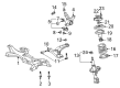
OEM 2003 Toyota Celica Control Arm
Suspension Arm- Select Vehicle by Model
- Select Vehicle by VIN
Select Vehicle by Model
orMake
Model
Year
Select Vehicle by VIN
For the most accurate results, select vehicle by your VIN (Vehicle Identification Number).
2 Control Arms found

 Product Specifications
- Other Name: Arm Sub-Assembly, Suspension; Suspension Control Arm, Front Left; Control Arm Assembly; Arm Sub-Assembly, Front Suspension, Lower Driver Side; Suspension Control Arm; Control Arm
- Position: Lower Driver Side
- Replaces: 48069-20380
- Part Name Code: 48069
- Item Weight: 7.40 Pounds
- Item Dimensions: 19.7 x 5.4 x 18.4 inches
- Condition: New
- Fitment Type: Direct Replacement
- SKU: 48069-20381
- Warranty: This genuine part is guaranteed by Toyota's factory warranty.
2003 Toyota Celica Lower Control Arm, Passenger Side
Part Number: 48068-20381$210.39 MSRP: $300.38You Save: $89.99 (30%)Product Specifications- Other Name: Arm Sub-Assembly, Suspension; Suspension Control Arm, Front Right; Control Arm Assembly; Arm Sub-Assembly, Front Suspension, Lower Passenger Side; Suspension Control Arm; Control Arm
- Position: Passenger Side
- Replaces: 48068-20380
- Part Name Code: 48068
- Item Weight: 9.10 Pounds
- Item Dimensions: 18.4 x 12.3 x 4.6 inches
- Condition: New
- Fitment Type: Direct Replacement
- SKU: 48068-20381
- Warranty: This genuine part is guaranteed by Toyota's factory warranty.
2003 Toyota Celica Control Arm
Looking for affordable OEM 2003 Toyota Celica Control Arm? Explore our comprehensive catalogue of genuine 2003 Toyota Celica Control Arm. All our parts are covered by the manufacturer's warranty. Plus, our straightforward return policy and speedy delivery service ensure an unparalleled shopping experience. We look forward to your visit!
2003 Toyota Celica Control Arm Parts Q&A
- Q: How to service and repair the lower control arm on 2003 Toyota Celica?A: The first step for repairing or servicing a lower control arm begins with removing the rear wheel at a torque value of 103 Nm (1,050 kgf-cm, 76 ft. lbs.). The next step requires the removal of the ABS speed sensor wire harness clamp and its bolt by hand while achieving a torque of 19 Nm (194 kgf-cm, 14 ft. lbs.). First disconnect the tailpipe using tools to remove its two bolts and springs as well as the gasket while managing three O-rings at 43 Nm (440 kgf-cm, 32 ft. lbs.). To disconnect the parking brake cable clamp remove its 2 bolts using a torque of 5.4 Nm (55 kgf-cm) or 48 inch lbs. Use a torque wrench to loosen the 3 bolts on the front side of the lower suspension arm to 65 Nm (663 kgf-cm, 48 ft. lbs.) without fully removing the bolts. Instillation requires restabilizing the suspension before torquing these bolts back. Begin disconnecting the rear axle carrier from the lower suspension arm through the following steps: use 74 Nm (55 kgf-cm, 55 ft. lbs.) torque to remove front side bolt and nut and mark the alignment points of cam plate and lower suspension arm before taking out the nut together with cam plate and cam bolt which require 74 Nm (755 kgf-cm, 55 ft. lbs.) torque for removal. Disassemble the rear shock absorber when you extract its bolt and nut while applying a torque of 140 Nm (1,428 kgf-cm, 103 ft. lbs.) then avoid twisting during installation since you need to tighten the bolt when the suspension is stable. The removal process starts by unfastening the rear-side bolt and nut with 74 Nm (755 kgf-cm, 55 ft. lbs.), then continuing to remove the front-side lower suspension arm 3 bolts with it. The operation to remove the suspension arm bracket includes disassembling the nut while also removing the bracket and stopper then tightening the nut to 110 Nm (1,122 kgf-cm, 81 ft. lbs.) before stabilizing the suspension. You need to verify rear wheel alignment following equipment installation.
Related 2003 Toyota Celica Parts
 2003 Toyota Celica Sway Bar Link
 2003 Toyota Celica Coil Springs
 2003 Toyota Celica Alignment Bolt
 2003 Toyota Celica Axle Shaft
 2003 Toyota Celica Control Arm Bolt
 2003 Toyota Celica Front Cross-Member
 2003 Toyota Celica Lateral Link
 2003 Toyota Celica Steering Knuckle
 2003 Toyota Celica Suspension Strut Rod
 2003 Toyota Celica Sway Bar Bracket
 2003 Toyota Celica Sway Bar Kit
 2003 Toyota Celica Wheel Seal