×
ToyotaParts- Hello
- Login or Register
- Quick Links
- Live Chat
- Track Order
- Parts Availability
- RMA
- Help Center
- Contact Us
- Shop for
- Toyota Parts
- Scion Parts
My Garage
My Account
Cart
OEM 2003 Toyota Celica Axle Shaft
Car Axle Shaft- Select Vehicle by Model
- Select Vehicle by VIN
Select Vehicle by Model
orMake
Model
Year
Select Vehicle by VIN
For the most accurate results, select vehicle by your VIN (Vehicle Identification Number).
13 Axle Shafts found

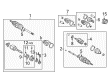
2003 Toyota Celica Shaft & Joint Assembly
Part Number: 43470-29725$237.85 MSRP: $339.59You Save: $101.74 (30%)Ships in 1-3 Business DaysProduct Specifications- Other Name: Shaft Assembly, Drive Outboard; Axle Shaft; CV Joint; Outer Joint Assembly
- Condition: New
- SKU: 43470-29725
- Warranty: This genuine part is guaranteed by Toyota's factory warranty.

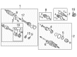
2003 Toyota Celica Axle Assembly, Passenger Side
Part Number: 43410-20800$468.03 MSRP: $685.90You Save: $217.87 (32%)Ships in 1-3 Business DaysProduct Specifications- Other Name: Shaft Assembly, Front Drive; CV Axle Assembly, Front Right; GSP Cv Axle; Axle Shaft; Shaft Assembly, Front Drive, Passenger Side; CV Axle Assembly
- Manufacturer Note: W(ABS)
- Position: Passenger Side
- Part Name Code: 43410
- Item Weight: 27.50 Pounds
- Item Dimensions: 43.3 x 5.5 x 5.5 inches
- Condition: New
- Fitment Type: Direct Replacement
- SKU: 43410-20800
- Warranty: This genuine part is guaranteed by Toyota's factory warranty.

2003 Toyota Celica Axle Assembly, Passenger Side
Part Number: 43410-20760$450.95 MSRP: $660.87You Save: $209.92 (32%)Ships in 1-3 Business DaysProduct Specifications- Other Name: Shaft Assembly, Front Drive; CV Axle Assembly, Front Right; Axle Shaft; Shaft Assembly, Front Drive, Passenger Side
- Position: Passenger Side
- Part Name Code: 43410
- Item Weight: 25.30 Pounds
- Item Dimensions: 43.7 x 5.6 x 5.5 inches
- Condition: New
- Fitment Type: Direct Replacement
- SKU: 43410-20760
- Warranty: This genuine part is guaranteed by Toyota's factory warranty.

2003 Toyota Celica Axle Assembly, Passenger Side
Part Number: 43410-20771$450.60 MSRP: $660.35You Save: $209.75 (32%)Ships in 1-3 Business DaysProduct Specifications- Other Name: Shaft Assembly, Front Drive; CV Axle Assembly, Front Right; GSP Cv Axle; Axle Shaft; Shaft Assembly, Front Drive, Passenger Side; CV Axle Assembly
- Position: Passenger Side
- Replaces: 43410-20770
- Part Name Code: 43410
- Item Weight: 19.20 Pounds
- Item Dimensions: 43.7 x 5.5 x 5.4 inches
- Condition: New
- Fitment Type: Direct Replacement
- SKU: 43410-20771
- Warranty: This genuine part is guaranteed by Toyota's factory warranty.
2003 Toyota Celica Axle Assembly, Passenger Side
Part Number: 43410-20781$449.71 MSRP: $659.06You Save: $209.35 (32%)Ships in 1-3 Business DaysProduct Specifications- Other Name: Shaft Assembly, Front Drive; CV Axle Assembly, Front Right; GSP Cv Axle; Axle Shaft; Shaft Assembly, Front Drive, Passenger Side; CV Axle Assembly
- Manufacturer Note: W(ABS)
- Position: Passenger Side
- Replaces: 43410-20780
- Part Name Code: 43410
- Item Weight: 21.70 Pounds
- Item Dimensions: 42.8 x 5.4 x 5.4 inches
- Condition: New
- Fitment Type: Direct Replacement
- SKU: 43410-20781
- Warranty: This genuine part is guaranteed by Toyota's factory warranty.
2003 Toyota Celica Axle Assembly, Passenger Side
Part Number: 43410-20600$449.01 MSRP: $658.03You Save: $209.02 (32%)Ships in 1-3 Business DaysProduct Specifications- Other Name: Shaft Assembly, Front Drive; CV Axle Assembly, Front Right; Axle Shaft; Shaft Assembly, Front Drive, Passenger Side
- Manufacturer Note: W(ABS)
- Position: Passenger Side
- Part Name Code: 43410
- Item Weight: 26.80 Pounds
- Item Dimensions: 42.8 x 5.4 x 5.6 inches
- Condition: New
- Fitment Type: Direct Replacement
- SKU: 43410-20600
- Warranty: This genuine part is guaranteed by Toyota's factory warranty.

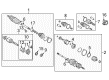
2003 Toyota Celica Axle Assembly, Driver Side
Part Number: 43420-20540$417.20 MSRP: $611.42You Save: $194.22 (32%)Ships in 1-3 Business DaysProduct Specifications- Other Name: Shaft Assembly, Front Drive; CV Axle Assembly, Front Left; GSP Cv Axle; Axle Shaft; Shaft Assembly, Front Drive, Driver Side; CV Axle Assembly
- Position: Driver Side
- Part Name Code: 43420
- Item Weight: 14.60 Pounds
- Item Dimensions: 29.2 x 7.5 x 6.6 inches
- Condition: New
- Fitment Type: Direct Replacement
- SKU: 43420-20540
- Warranty: This genuine part is guaranteed by Toyota's factory warranty.

2003 Toyota Celica Axle Assembly, Driver Side
Part Number: 43420-20571$397.36 MSRP: $582.35You Save: $184.99 (32%)Ships in 1-3 Business DaysProduct Specifications- Other Name: Shaft Assembly, Front Drive; CV Axle Assembly, Front Left; GSP Cv Axle; Axle Shaft; Shaft Assembly, Front Drive, Driver Side; CV Axle Assembly
- Position: Driver Side
- Replaces: 43420-20570
- Part Name Code: 43420
- Item Weight: 14.60 Pounds
- Item Dimensions: 31.3 x 5.1 x 5.1 inches
- Condition: New
- Fitment Type: Direct Replacement
- SKU: 43420-20571
- Warranty: This genuine part is guaranteed by Toyota's factory warranty.

2003 Toyota Celica Axle Assembly, Driver Side
Part Number: 43420-20550$397.36 MSRP: $582.35You Save: $184.99 (32%)Ships in 1-3 Business DaysProduct Specifications- Other Name: Shaft Assembly, Front Drive; CV Axle Assembly, Front Left; Axle Shaft; Shaft Assembly, Front Drive, Driver Side
- Position: Driver Side
- Part Name Code: 43420
- Item Weight: 14.10 Pounds
- Item Dimensions: 28.9 x 7.5 x 6.5 inches
- Condition: New
- Fitment Type: Direct Replacement
- SKU: 43420-20550
- Warranty: This genuine part is guaranteed by Toyota's factory warranty.
2003 Toyota Celica Axle Assembly, Driver Side
Part Number: 43420-20581$396.85 MSRP: $581.60You Save: $184.75 (32%)Ships in 1-3 Business DaysProduct Specifications- Other Name: Shaft Assembly, Front Drive; CV Axle Assembly, Front Left; GSP Cv Axle; Axle Shaft; Shaft Assembly, Front Drive, Driver Side; CV Axle Assembly
- Manufacturer Note: W(ABS)
- Position: Driver Side
- Replaces: 43420-20580
- Part Name Code: 43420
- Item Weight: 14.30 Pounds
- Item Dimensions: 30.4 x 5.3 x 5.1 inches
- Condition: New
- Fitment Type: Direct Replacement
- SKU: 43420-20581
- Warranty: This genuine part is guaranteed by Toyota's factory warranty.
2003 Toyota Celica Axle Assembly, Driver Side
Part Number: 43420-20560$396.72 MSRP: $581.40You Save: $184.68 (32%)Ships in 1-3 Business DaysProduct Specifications- Other Name: Shaft Assembly, Front Drive; CV Axle Assembly, Front Left; Axle Shaft; Shaft Assembly, Front Drive, Driver Side
- Manufacturer Note: W(ABS)
- Position: Driver Side
- Part Name Code: 43420
- Item Weight: 27.30 Pounds
- Item Dimensions: 31.0 x 5.3 x 5.3 inches
- Condition: New
- Fitment Type: Direct Replacement
- SKU: 43420-20560
- Warranty: This genuine part is guaranteed by Toyota's factory warranty.
- Product Specifications
- Other Name: Shaft Assembly, Front Drive; CV Axle Assembly, Front Right; GSP Cv Axle; Axle Shaft; Shaft Assembly, Front Drive, Passenger Side; CV Axle Assembly
- Position: Passenger Side
- Part Name Code: 43410
- Item Weight: 27.30 Pounds
- Item Dimensions: 43.7 x 5.6 x 5.4 inches
- Condition: New
- Fitment Type: Direct Replacement
- SKU: 43410-20790
- Warranty: This genuine part is guaranteed by Toyota's factory warranty.
- Product Specifications
- Other Name: Shaft Assembly, Front Drive; CV Axle Assembly, Front Left; GSP Cv Axle; Axle Shaft; Shaft Assembly, Front Drive, Driver Side; CV Axle Assembly
- Manufacturer Note: W(ABS)
- Position: Driver Side
- Part Name Code: 43420
- Item Weight: 26.80 Pounds
- Item Dimensions: 29.8 x 5.2 x 5.2 inches
- Condition: New
- Fitment Type: Direct Replacement
- SKU: 43420-20590
- Warranty: This genuine part is guaranteed by Toyota's factory warranty.
2003 Toyota Celica Axle Shaft
Looking for affordable OEM 2003 Toyota Celica Axle Shaft? Explore our comprehensive catalogue of genuine 2003 Toyota Celica Axle Shaft. All our parts are covered by the manufacturer's warranty. Plus, our straightforward return policy and speedy delivery service ensure an unparalleled shopping experience. We look forward to your visit!
2003 Toyota Celica Axle Shaft Parts Q&A
- Q: How to service and repair the axle shaft on 2003 Toyota Celica?A: Service and repair of axle shafts starts with disassembly that includes measuring outboard joint play, testing inboard joint smoothness in thrust movements as well as radial checks of the inboard joint along with boot damage inspection. The inboard joint boot clamps need screwdriver removal while side cutters work for outboard clamp removal. When working with manual transmission you can separate the dynamic damper clamp using a screwdriver to move the inboard joint boot toward the outboard joint while marking both shafts but omitting holes in the mark positions. The mechanic should remove the snap ring to separate the inboard joint shaft from the outboard joint shaft. The outboard joint shaft needs disassembly through marking the inner race and cage then removing the balls followed by sliding the cage before extracting the inner race with a snap ring expander and brass bar. Separate and store the dynamic damper as well as all the joint clamps and boots from both inboard and outboard units but avoid breaking down any parts of the outboard joint. An automatic transmission drive shaft installation process matches the inboard joint shaft removal procedure by making matchmarks before removal. You should take the tripod out using both a snap ring expander tool and a brass bar but avoid hitting the roller during the operation. Special Service Tool: 09950-00020 installed with a press system will remove the inboard joint shaft dust cover while the right-hand side needs a screwdriver, press, and pin punch to remove the transaxle side dust cover and center bearing. For left-hand side reassembly use a press to install a new dust cover while proper installation tools should be used for center bearing and snap rings on the right-hand side. Install new inboard and outboard joint boots and clamps as a temporary step while vinyl tape must be wrapped around the outboard joint shaft spline. The system requires installing the tripod under correct alignment using matchmarks while tapping it with a brass bar before filling outboard joint and boot with grease at the proper capacity. Begin with joint shaft assembly where both pieces are packed with grease and aligned matchmarks receive a new snap ring. Install the boot clamps while making sure boots fit correctly and avoiding stretching by using Special Service Tool: 09521-24010 and 09240-00020 to set clamp clearance. The installation of the dynamic damper clamp for manual transmission should begin with setting the distance to 155.0 plus or minus 2.0 mm followed by clamp locking. The drive shaft assembly requires one final inspection of all its components for appropriate construction and operational quality.
Related 2003 Toyota Celica Parts
 2003 Toyota Celica CV Joint
 2003 Toyota Celica Control Arm
 2003 Toyota Celica Sway Bar Link
 2003 Toyota Celica Coil Springs
 2003 Toyota Celica Coil Spring Insulator
 2003 Toyota Celica Lateral Link
 2003 Toyota Celica Rear Crossmember
 2003 Toyota Celica Shock And Strut Mount
 2003 Toyota Celica Suspension Strut Rod
 2003 Toyota Celica Sway Bar Bracket
 2003 Toyota Celica Sway Bar Kit
 2003 Toyota Celica Wheel Seal