- Hello
- Login or Register
- Quick Links
- Live Chat
- Track Order
- Parts Availability
- RMA
- Help Center
- Contact Us
- Shop for
- Toyota Parts
- Scion Parts

Popular OEM Toyota Celica Parts
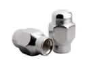
- Body & Hardware Parts View More >
- Electrical Parts View More >
- Engine Parts View More >
- Air & Fuel Delivery Parts View More >
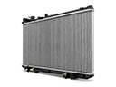
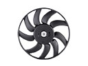
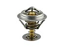
- Belts & Cooling Parts View More >
- Steering Parts View More >
- Suspension Parts View More >
- Emission Control & Exhaust Parts View More >
- A/C & Heating Parts View More >
- Charging & Starting Parts View More >
- Brakes Parts View More >
- Transmission Parts View More >


Why Buy Genuine Toyota Celica Parts From ToyotaPartsNow.com
ToyotaPartsNow.com highlights the reliability of OEM Toyota Celica parts right at your fingertips. Our skilled staff assists customers in selecting the right Toyota Celica parts and provides expert help with any unique part requests. At ToyotaPartsNow.com, we make all Toyota Celica parts available to you quickly and efficiently through our fast order and reliable ship process. Our service is designed to make finding the correct Toyota Celica parts fast and easy whether you are an amateur or a professional. We offer access to a broad inventory that includes a wide range of Toyota years and variants. Affordable prices, quick processing and professional service are also our specialty to ensure your car remains in top condition with OEM Toyota Celica parts, including Headlights & Lighting. You can feel confident shopping with us because all Toyota Celica parts, such as Driveline & Axles you purchase from our store are of genuine quality and built to last.
The Toyota Celica arrived on the market in 1973 as a sporty coupe that utilized shared components from Toyota's Corona to produce a compact and versatile vehicle. The 1.6-liter 2T engine in the 1973 original Celica delivered excellent performance and fuel efficiency while winners of Best of Show received a 2T-B engine from 1974 featuring better emissions. The first automatic Celica featured the smooth-shifting 4R automatic transmission known as the A40 in North American ST and LT models. The 1975 model year introduced redesigned heavy bumpers that satisfied federal safety standards and provided enhanced protection against low-speed collisions. The 1978 Celica utilized a 2.2-liter 20R engine to achieve better performance and improved fuel economy compared to previous models. Product work included: Frame removal from windows required additional B-Rail thickness to achieve structural stability. The GTV version of the Toyota Celica offered an enhanced driving experience through its stiffer suspension which served to boost safety control performance. Toyota maintains strict quality standards to produce Celica OE parts which ensure durability and maximum performance. The company fulfills its quality promise by distributing OEM parts through Toyota dealer networks which are built to decompose.
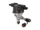
The Toyota Celica is known among drivers for its solid performance. But some owners have mechanical issues that reduce the reliability of the vehicle. The Toyota Celica automatic transmission has a pretty typical issue. It doesn't shift well when it has a lot of miles on it. The usual culprit for this problem is a misadjusted Toyota Celica throttle position sensor. It could also be a bad shift solenoid. The Toyota Celica transmission doesn't need a full rebuild most of the time. The other problem is the ignition. The distributor holds the Toyota Celica ignition coil. The coil can malfunction, causing hesitation, poor acceleration or a no-start condition especially in cold or wet weather. A technician will replace the entire distributor with a genuine Toyota part if an internal component fails. Lastly, other possible power steering issues could be leaks of power steering hoses or the power steering pump. It may require the replacement of power steering pump and hoses. To make sure that the Toyota Celica stays in peak condition, owners need regular maintenance along with quick repairs.
Toyota Celica Parts and Q&A
- Q: How to service and repair the water pump on Toyota Celica?A:To service the water pump, undo the cover of the RH engine, empty the coolant and extract the drive belt. In the case of the 1ZZ-FE engine, water-pump and O-ring are stripped off, clean the chamber and apply a new O-ring. In the case of the 2ZZ-GE engine special tools should be used to install it. Look at the coolant when returning to work.
- Q: How to remove the timing chain on Toyota Celica?A:Remove upper fender and radiator seals, drain coolant, remove wheel. For 2ZZ-GE remove air valve, belt and generator. Disconnect and suspend PS pump, remove engine mount and cylinder head cover parts, set No.1 to TDC, remove pulley, sensors, tensioners, chain, sprockets and valve timing assembly.
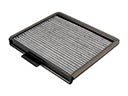
- Q: How to replace the Cabin Air Filter on Toyota Celica?A:In order to install the air refiner filter, it is necessary to take off the 2 pins in the glove box and break it open. Exchange the old filter with the current filter. Install the new filter back into the case and pop in again and close the glove box using the pins.


