×
ToyotaParts- Hello
- Login or Register
- Quick Links
- Live Chat
- Track Order
- Parts Availability
- RMA
- Help Center
- Contact Us
- Shop for
- Toyota Parts
- Scion Parts
My Garage
My Account
Cart
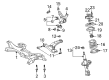
OEM 2005 Toyota Celica Control Arm
Suspension Arm- Select Vehicle by Model
- Select Vehicle by VIN
Select Vehicle by Model
orMake
Model
Year
Select Vehicle by VIN
For the most accurate results, select vehicle by your VIN (Vehicle Identification Number).
2 Control Arms found

 Product Specifications
- Other Name: Arm Sub-Assembly, Suspension; Suspension Control Arm, Front Left; Control Arm Assembly; Arm Sub-Assembly, Front Suspension, Lower Driver Side; Suspension Control Arm; Control Arm
- Position: Lower Driver Side
- Replaces: 48069-20380
- Part Name Code: 48069
- Item Weight: 7.40 Pounds
- Item Dimensions: 19.7 x 5.4 x 18.4 inches
- Condition: New
- Fitment Type: Direct Replacement
- SKU: 48069-20381
- Warranty: This genuine part is guaranteed by Toyota's factory warranty.
2005 Toyota Celica Lower Control Arm, Passenger Side
Part Number: 48068-20381$210.39 MSRP: $300.38You Save: $89.99 (30%)Product Specifications- Other Name: Arm Sub-Assembly, Suspension; Suspension Control Arm, Front Right; Control Arm Assembly; Arm Sub-Assembly, Front Suspension, Lower Passenger Side; Suspension Control Arm; Control Arm
- Position: Passenger Side
- Replaces: 48068-20380
- Part Name Code: 48068
- Item Weight: 9.10 Pounds
- Item Dimensions: 18.4 x 12.3 x 4.6 inches
- Condition: New
- Fitment Type: Direct Replacement
- SKU: 48068-20381
- Warranty: This genuine part is guaranteed by Toyota's factory warranty.
2005 Toyota Celica Control Arm
Looking for affordable OEM 2005 Toyota Celica Control Arm? Explore our comprehensive catalogue of genuine 2005 Toyota Celica Control Arm. All our parts are covered by the manufacturer's warranty. Plus, our straightforward return policy and speedy delivery service ensure an unparalleled shopping experience. We look forward to your visit!
2005 Toyota Celica Control Arm Parts Q&A
- Q: How to service and repair the front control arm on 2005 Toyota Celica?A: Service and repair operations on the front control arm should start by removing the front wheel while applying torque of 103 Nm (1,050 kgf-cm, 76 ft. lbs.). Service providers must start by removing the engine under cover before using appropriate tools to disconnect the lower suspension arm from the lower ball joint by removing the bolt and 2 nuts with 142 Nm (1,450 kgf-cm, 105 ft. lbs.) torque. Remove the 2 bolts and nut alongside the lower suspension arm while applying torque force of 137 Nm (1,397 kgf-cm, 101 ft. lbs.). Keep in mind to actually torque the bolts once you stabilize the suspension during assembly. Start by removing the engine under covers on the A/T LH side. Then twist the RH and LH tie rod ends from the steering knuckle by removing their cotter pin and nut while tightening the nut to 49 Nm (500 kgf-cm, 36 ft. lbs.) but maintaining a further up to 60° torque if the new cotter pin holes are not aligned. Use Special Service Tool: 09610-20012 to detach the steering knuckle tie rod end before repeating the procedure on the other side. To disconnect the RH and LH stabilizer bar links, remove the nut and detach them from the shock absorber with a torque of 44 Nm (449 kgf-cm, 32 ft. lbs.) while using a hexagon (5 mm) wrench to maintain the stud if the ball joint rotates with the nut. Rollers off the lower ball joints of both RH and LH suspension arms by loosening bolt and 2 nuts with 142 Nm torque and perform the same steps on the opposite side. Loosen the lower suspension arm set bolts with a torque of 137 Nm (1,397 kgf-cm, 101 ft. lbs.), then remove the engine hood and attach the engine sling device to the engine hangers, disconnecting the 2 PCV hoses and installing the No. 1 and No. 2 engine hangers in the correct direction, using part numbers 12281-22021 and 12281-15040 or 12281-15050 for the 1Z-FE engine, and 12281-88600 and 12282-88600 for the 2Z-GE engine, with bolt 91512-B1016 or 91512-61020, applying a torque of 38 Nm (387 kgf-cm, 28 ft. lbs.). Hook the engine chain hoist to the engine hangers but never suspend the engine on any other part. Remove the 4 set bolts from the PS gear assembly to suspension member connection with a torque of 58 Nm (591 kgf-cm, 43 ft. lbs.) while supporting the PS gear assembly properly. Start by removing bolt A and 3 nuts to detach the engine rear mount which requires a torque of 52 Nm (530 kgf-cm, 38 ft. lbs.). Then remove the 2 bolts (B) for engine front mount disconnect with the same torque value. Support the suspension member by attaching a transmission jack before you remove six bolts (C and D) that require a torque of 157 Nm (1,600 kgf-cm, 116 ft. lbs.) for bolt C and 39 Nm (400 kgf-cm, 29 ft. lbs.) for bolt D. After that, remove the 2 bolts, nut, and lower suspension arm. The installation sequence operates in the opposite direction of removal steps and wheel front alignment check should follow the completion of installation.
Related 2005 Toyota Celica Parts
 2005 Toyota Celica Sway Bar Link
 2005 Toyota Celica Coil Springs
 2005 Toyota Celica Alignment Bolt
 2005 Toyota Celica Axle Shaft
 2005 Toyota Celica Control Arm Bolt
 2005 Toyota Celica Front Cross-Member
 2005 Toyota Celica Lateral Link
 2005 Toyota Celica Steering Knuckle
 2005 Toyota Celica Suspension Strut Rod
 2005 Toyota Celica Sway Bar Bracket
 2005 Toyota Celica Sway Bar Kit
 2005 Toyota Celica Wheel Seal