×
ToyotaParts- Hello
- Login or Register
- Quick Links
- Live Chat
- Track Order
- Parts Availability
- RMA
- Help Center
- Contact Us
- Shop for
- Toyota Parts
- Scion Parts
My Garage
My Account
Cart
OEM Toyota Echo Control Arm
Suspension Arm- Select Vehicle by Model
- Select Vehicle by VIN
Select Vehicle by Model
orMake
Model
Year
Select Vehicle by VIN
For the most accurate results, select vehicle by your VIN (Vehicle Identification Number).
4 Control Arms found

Toyota Echo Lower Control Arm, Driver Side Part Number: 48069-59035
$234.88 MSRP: $335.35You Save: $100.47 (30%)Ships in 1-3 Business DaysToyota Echo Lower Control Arm, Passenger Side Part Number: 48068-59035
$234.88 MSRP: $335.35You Save: $100.47 (30%)Ships in 1-3 Business DaysToyota Echo Lower Control Arm, Driver Side Part Number: 48069-59055
$262.81 MSRP: $375.24You Save: $112.43 (30%)Ships in 1-3 Business DaysToyota Echo Lower Control Arm, Passenger Side Part Number: 48068-59055
$285.53 MSRP: $407.67You Save: $122.14 (30%)Ships in 1-3 Business Days
Toyota Echo Control Arm
Choose genuine Control Arm that pass strict quality control tests. You can trust the top quality and lasting durability. Shopping for OEM Control Arm for your Toyota Echo? Our website is your one-stop destination. We stock an extensive selection of genuine Toyota Echo parts. The price is affordable so you can save more. It only takes minutes to browse and find the exact fit. Easily add to cart and check out fast. Our hassle-free return policy will keep you stress-free. We process orders quickly for swift delivery. Your parts will arrive faster, so you can get back on the road sooner.
Toyota Echo Control Arm Parts and Q&A
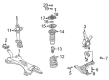
- Q: How to remove and install the control arm on Toyota Echo?A:Beginning the control arm removal requires first removing the front wheel and the stabilizer bar link by holding it and removing 2 nuts and 5 retainers along with 4 cushions before extracting the link itself. The process begins by removing the clip as well as the nut for steering knuckle disconnection. To safely complete this step use Special Service Tool: 09628-00011 (09628-00030, 09628-00040, 09628-00050). When dealing with the right-hand arm you must begin by raising the engine slightly through the removal of its bolt along with two nuts that enable engine rear mount disconnect. Following this step use a transmission jack along with a wooden block to suspend the engine. Make sure to avoid jacking pressure on the oil pan. Remove the lower suspension arm through the removal of its 2 bolts and nut while preventing the nut rotation. The ball joint rotation limits are checked by operating the ball joint stud back and forth 5 times before nut installation followed by torque wrench measurement on the 5th turn where the torque should be between 0.59 - 3.43 Nm (6 - 35 kgf-cm, 5.2 - 30 inch lbs.). Installation requires attaching the lower suspension arm with its 2 bolts and torquing Bolt A to 88 Nm (900 kgf-cm, 65 ft. lbs.) and Bolt B to 132 Nm (1,350 kgf-cm, 97 ft. lbs.) without turning the nut while stabilizing the suspension to complete the bolt torquing process. Fasten the engine rear mount using both the bolt and its 2 accompanying nuts before torquing them to 80 Nm (810 kgf-cm, 59 ft. lbs.). The lower suspension arm should be fitted to the steering knuckle using a nut followed by torquing to 98 Nm (1,000 kgf-cm, 72 ft. lbs.) before adding a new clip that requires further nut tightening by 60° during misaligned clip hole installation. The stabilizer bar link must be installed together with four cushions and five retainers, using two nuts that must be torqued to 18 Nm (180 kgf-cm, 13 ft. lbs.). Finally, install the front wheel with 103 Nm (1,050 kgf-cm, 76 ft. lbs.) torque, then inspect the front wheel alignment.

Related Toyota Echo Parts
 Toyota Echo Axle Beam Mount
 Toyota Echo Bump Stop
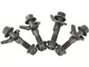 Toyota Echo Camber and Alignment Kit
 Toyota Echo Coil Spring Insulator
 Toyota Echo Coil Springs
 Toyota Echo Control Arm Bolt
 Toyota Echo Front Cross-Member
 Toyota Echo Shock and Strut Boot
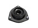 Toyota Echo Strut Mounts
 Toyota Echo Sway Bar Bracket
 Toyota Echo Sway Bar Bushing
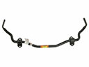 Toyota Echo Sway Bars
Browse Toyota Echo Control Arm by Years
2005
2004
2003
2002
2001
2000