×
ToyotaParts- Hello
- Login or Register
- Quick Links
- Live Chat
- Track Order
- Parts Availability
- RMA
- Help Center
- Contact Us
- Shop for
- Toyota Parts
- Scion Parts
My Garage
My Account
Cart
OEM 2001 Toyota Echo Control Arm
Suspension Arm- Select Vehicle by Model
- Select Vehicle by VIN
Select Vehicle by Model
orMake
Model
Year
Select Vehicle by VIN
For the most accurate results, select vehicle by your VIN (Vehicle Identification Number).
2 Control Arms found

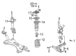
2001 Toyota Echo Lower Control Arm, Driver Side
Part Number: 48069-59035$234.88 MSRP: $335.35You Save: $100.47 (30%)Ships in 1-3 Business DaysProduct Specifications- Other Name: Arm Sub-Assembly, Suspension; Suspension Control Arm, Front Left; Control Arm Assembly; Track Control Arm; Arm Sub-Assembly, Front Suspension, Lower Driver Side; Control Arm
- Position: Lower Driver Side
- Part Name Code: 48069
- Item Weight: 1.70 Pounds
- Item Dimensions: 25.5 x 4.1 x 13.0 inches
- Condition: New
- Fitment Type: Direct Replacement
- SKU: 48069-59035
- Warranty: This genuine part is guaranteed by Toyota's factory warranty.
2001 Toyota Echo Lower Control Arm, Passenger Side
Part Number: 48068-59035$234.88 MSRP: $335.35You Save: $100.47 (30%)Ships in 1-3 Business DaysProduct Specifications- Other Name: Arm Sub-Assembly, Suspension; Suspension Control Arm, Front Right; Control Arm Assembly; Track Control Arm; Arm Sub-Assembly, Front Suspension, Lower Passenger Side; Control Arm
- Position: Passenger Side
- Part Name Code: 48068
- Item Weight: 1.70 Pounds
- Item Dimensions: 25.3 x 4.1 x 12.6 inches
- Condition: New
- Fitment Type: Direct Replacement
- SKU: 48068-59035
- Warranty: This genuine part is guaranteed by Toyota's factory warranty.
2001 Toyota Echo Control Arm
Looking for affordable OEM 2001 Toyota Echo Control Arm? Explore our comprehensive catalogue of genuine 2001 Toyota Echo Control Arm. All our parts are covered by the manufacturer's warranty. Plus, our straightforward return policy and speedy delivery service ensure an unparalleled shopping experience. We look forward to your visit!
2001 Toyota Echo Control Arm Parts Q&A
- Q: How to remove and install the control arm on 2001 Toyota Echo?A: To remove the control arm, detach the front wheel and stabilizer bar link. Disconnect the lower suspension arm from the steering knuckle, then jack up the engine to remove the lower suspension arm. Inspect the ball joint, install the arm, and torque all components as specified, finishing with the front wheel alignment check.
Related 2001 Toyota Echo Parts
 2001 Toyota Echo Alignment Bolt
 2001 Toyota Echo Axle Beam Mount
 2001 Toyota Echo Bump Stop
 2001 Toyota Echo Coil Springs
 2001 Toyota Echo Control Arm Bolt
 2001 Toyota Echo Shock Absorber
 2001 Toyota Echo Shock And Strut Mount
 2001 Toyota Echo Shock and Strut Boot
 2001 Toyota Echo Steering Knuckle
 2001 Toyota Echo Sway Bar Bracket
 2001 Toyota Echo Sway Bar Bushing
 2001 Toyota Echo Sway Bar Kit