×
ToyotaParts- Hello
- Login or Register
- Quick Links
- Live Chat
- Track Order
- Parts Availability
- RMA
- Help Center
- Contact Us
- Shop for
- Toyota Parts
- Scion Parts
My Garage
My Account
Cart
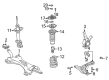
OEM 2000 Toyota Echo Control Arm
Suspension Arm- Select Vehicle by Model
- Select Vehicle by VIN
Select Vehicle by Model
orMake
Model
Year
Select Vehicle by VIN
For the most accurate results, select vehicle by your VIN (Vehicle Identification Number).
2 Control Arms found

2000 Toyota Echo Lower Control Arm, Driver Side
Part Number: 48069-59035$234.88 MSRP: $335.35You Save: $100.47 (30%)Ships in 1-3 Business DaysProduct Specifications- Other Name: Arm Sub-Assembly, Suspension; Suspension Control Arm, Front Left; Control Arm Assembly; Track Control Arm; Arm Sub-Assembly, Front Suspension, Lower Driver Side; Control Arm
- Position: Lower Driver Side
- Part Name Code: 48069
- Item Weight: 1.70 Pounds
- Item Dimensions: 25.5 x 4.1 x 13.0 inches
- Condition: New
- Fitment Type: Direct Replacement
- SKU: 48069-59035
- Warranty: This genuine part is guaranteed by Toyota's factory warranty.
2000 Toyota Echo Lower Control Arm, Passenger Side
Part Number: 48068-59035$234.88 MSRP: $335.35You Save: $100.47 (30%)Ships in 1-3 Business DaysProduct Specifications- Other Name: Arm Sub-Assembly, Suspension; Suspension Control Arm, Front Right; Control Arm Assembly; Track Control Arm; Arm Sub-Assembly, Front Suspension, Lower Passenger Side; Control Arm
- Position: Passenger Side
- Part Name Code: 48068
- Item Weight: 1.70 Pounds
- Item Dimensions: 25.3 x 4.1 x 12.6 inches
- Condition: New
- Fitment Type: Direct Replacement
- SKU: 48068-59035
- Warranty: This genuine part is guaranteed by Toyota's factory warranty.
2000 Toyota Echo Control Arm
Looking for affordable OEM 2000 Toyota Echo Control Arm? Explore our comprehensive catalogue of genuine 2000 Toyota Echo Control Arm. All our parts are covered by the manufacturer's warranty. Plus, our straightforward return policy and speedy delivery service ensure an unparalleled shopping experience. We look forward to your visit!
2000 Toyota Echo Control Arm Parts Q&A
- Q: How to remove and install the control arm on 2000 Toyota Echo?A: Begin control arm removal by removing the front wheel followed by disconnecting the stabilizer bar link by holding it while unscrewing its 2 nuts followed by removal of 5 retainers, 4 cushions and finally the link itself. The special service tool number 09628-00011 (09628-00030, 09628-00040, 09628-00050) is essential for disconnecting the lower suspension arm from its attachment to the steering knuckle. Before using the tool you need to remove the clip then the nut. Differentiate the right-hand arm by lifting the engine slightly after you detach the bolt along with the 2 nuts from the engine rear mount. Avoid lifting pressure on the oil pan. The removal of the lower suspension arm begins with unscrewing its two bolts and nut then removing the part itself while avoiding the rotation of the nut. Before installing the nut on the ball joint strike the ball joint stud back and forth five times to inspect its rotation before applying a torque at 0.59 - 3.43 Nm (6 - 35 kgf.cm, 5.2 - 30 inch lbs.) within five turns using a torque wrench. The installation process involves attaching the lower suspension arm with 2 bolts and torquing Bolt A to 88 Nm (900 kgf.cm, 65 ft. lbs.) while torquing Bolt B to 132 Nm (1,350 kgf.cm, 97 ft. lbs.). During the process, refrain from rotating the nut and keep the suspension stable before tightening. Use the bolt to link the engine rear mount to two nuts while torquing them up to 80 Nm (810 kgf.cm, 59 ft. lbs.). Use a new nut to join the lower suspension arm to the steering knuckle while torquing it to 98 Nm (1,000 kgf.cm, 72 ft. lbs.). When necessary, the alignment of the clip holes requires tightening the nut up to 60 degrees before installing the new clip. You must install the stabilizer bar link with all 4 cushions and 5 retainers using 2 nuts which require a torques setting of 18 Nm (180 kgf.cm, 13 ft. lbs.). After completing this step reinstall the front wheel and torque it to 103 Nm (1,050 kgf.cm, 76 ft. lbs.). Finally, perform a front wheel alignment check.
Related 2000 Toyota Echo Parts
 2000 Toyota Echo Alignment Bolt
 2000 Toyota Echo Axle Beam Mount
 2000 Toyota Echo Bump Stop
 2000 Toyota Echo Coil Springs
 2000 Toyota Echo Control Arm Bolt
 2000 Toyota Echo Shock Absorber
 2000 Toyota Echo Shock And Strut Mount
 2000 Toyota Echo Shock and Strut Boot
 2000 Toyota Echo Steering Knuckle
 2000 Toyota Echo Sway Bar Bracket
 2000 Toyota Echo Sway Bar Bushing
 2000 Toyota Echo Sway Bar Kit