×
ToyotaParts- Hello
- Login or Register
- Quick Links
- Live Chat
- Track Order
- Parts Availability
- RMA
- Help Center
- Contact Us
- Shop for
- Toyota Parts
- Scion Parts
My Garage
My Account
Cart
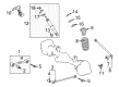
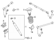
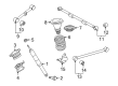
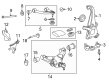
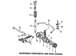
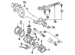
OEM Toyota Land Cruiser Control Arm
Suspension Arm- Select Vehicle by Model
- Select Vehicle by VIN
Select Vehicle by Model
orMake
Model
Year
Select Vehicle by VIN
For the most accurate results, select vehicle by your VIN (Vehicle Identification Number).
22 Control Arms found


Toyota Land Cruiser Upper Control Arm, Passenger Side Part Number: 48610-60060
$301.84 MSRP: $430.96You Save: $129.12 (30%)Ships in 1-3 Business Days


Toyota Land Cruiser Lower Control Arm, Passenger Side Part Number: 48620-60010
$322.51 MSRP: $460.47You Save: $137.96 (30%)Ships in 1-3 Business Days


Toyota Land Cruiser Upper Control Arm, Passenger Side Part Number: 48610-60030
$354.34 MSRP: $519.28You Save: $164.94 (32%)Ships in 1-3 Business Days


Toyota Land Cruiser Arm Assembly, Front Suspension, Upper Driver Side Part Number: 48630-60010
$354.34 MSRP: $519.28You Save: $164.94 (32%)Ships in 1-3 Business Days

Toyota Land Cruiser Upper Control Arm, Rear Driver Side Part Number: 48710-60150
$142.75 MSRP: $202.08You Save: $59.33 (30%)Ships in 1-3 Business Days
Toyota Land Cruiser Upper Control Arm, Driver Side Part Number: 48630-60030
$301.84 MSRP: $430.96You Save: $129.12 (30%)Ships in 1-3 Business Days

Toyota Land Cruiser Lower Control Arm, Passenger Side Part Number: 48068-35051
$204.76 MSRP: $292.35You Save: $87.59 (30%)Ships in 1-3 Business Days


Toyota Land Cruiser Lower Control Arm, Driver Side Part Number: 48069-35051
$236.83 MSRP: $338.14You Save: $101.31 (30%)Ships in 1-3 Business Days

Toyota Land Cruiser Upper Control Arm, Driver Side Part Number: 48067-35060
$314.19 MSRP: $448.59You Save: $134.40 (30%)Ships in 1-3 Business Days
Toyota Land Cruiser Arm Assembly, Upper Control, Rear Driver Side Part Number: 48710-60131
$138.76 MSRP: $196.43You Save: $57.67 (30%)Ships in 1-3 Business Days
Toyota Land Cruiser Arm Assembly, Upper Control Part Number: 48710-60230
$155.68 MSRP: $220.38You Save: $64.70 (30%)Ships in 1-2 Business Days
Toyota Land Cruiser Arm Assembly, Upper Control Part Number: 48710-60220
$155.68 MSRP: $220.38You Save: $64.70 (30%)Ships in 1-2 Business Days
Toyota Land Cruiser Arm Assembly, Suspension Part Number: 48630-60100
$256.17 MSRP: $365.75You Save: $109.58 (30%)
Toyota Land Cruiser Arm Sub-Assembly, Suspension Part Number: 48069-60080
$340.83 MSRP: $499.49You Save: $158.66 (32%)Toyota Land Cruiser Arm Sub-Assembly, Suspension Part Number: 48068-60080
$340.83 MSRP: $499.49You Save: $158.66 (32%)
Toyota Land Cruiser Arm Assembly, Leading, Front Part Number: 48610-60022
$336.91 MSRP: $481.03You Save: $144.12 (30%)Ships in 1-3 Business Days


Toyota Land Cruiser Arm Sub-Assembly, Front Suspension, Lower Passenger Side Part Number: 48068-60030
$288.89 MSRP: $412.46You Save: $123.57 (30%)
Toyota Land Cruiser Arm Sub-Assembly, Front Suspension, Lower Driver Side Part Number: 48069-60030
$285.70 MSRP: $407.92You Save: $122.22 (30%)


Toyota Land Cruiser Upper Control Arm, Passenger Side Part Number: 48066-35110
$314.19 MSRP: $448.59You Save: $134.40 (30%)
Toyota Land Cruiser Arm Assembly, Front Part Number: 48610-60021
$358.42 MSRP: $525.27You Save: $166.85 (32%)
| Page 1 of 2 |Next >
1-20 of 22 Results
Toyota Land Cruiser Control Arm
Choose genuine Control Arm that pass strict quality control tests. You can trust the top quality and lasting durability. Shopping for OEM Control Arm for your Toyota Land Cruiser? Our website is your one-stop destination. We stock an extensive selection of genuine Toyota Land Cruiser parts. The price is affordable so you can save more. It only takes minutes to browse and find the exact fit. Easily add to cart and check out fast. Our hassle-free return policy will keep you stress-free. We process orders quickly for swift delivery. Your parts will arrive faster, so you can get back on the road sooner.
Toyota Land Cruiser Control Arm Parts and Q&A
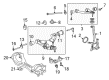
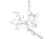
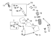
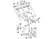
- Q: How to install the front lower control arm on Toyota Land Cruiser?A:To install the front lower suspension arm, begin by temporarily installing the front NO. 1 suspension arm lower sub-assembly LH by securing the lower suspension arm, camber adjusting cam, NO. 2 camber adjusting cam, NO. 2 suspension toe adjusting plate, toe adjusting cam, and washer with the bolt and nut, ensuring the matchmarks on the NO. 2 camber adjusting cam and NO. 2 suspension toe adjusting plate align with those on the vehicle body before tightening the bolt and nut to the specified torque in the tightening procedure. First lift the front lower ball joint attachment LH into position on the Steering Knuckle then secure it with 2 bolts that you tighten to 300 Nm (3059 kgf-cm, 221 ft-lbf). Afterwards, join the front Shock Absorber with coil spring LH attachment with its bolt and nut. First put on the front stabilizer link assembly RH and LH for temporary installation before securing the front NO. 1 stabilizer bracket LH and RH. Place the NO. 1 engine under cover sub-assembly and both front fender splash shield sub-assembles LH and RH into position. First stabilize the suspension and then apply torque to the front NO. 1 suspension arm lower sub-assembly LH bolt and nut to 280 Nm (2855 kgf-cm, 207 ft-lbf) while keeping all 4 wheels on the ground before torquing the front shock absorber with coil spring nut to 180 Nm (1835 kgf-cm, 133 ft-lbf) using the same ground position. Screw in both front stabilizer link assembly LH and RH nut plates and check vehicle height once the stabilizer control valve is turned off by moving the valve within the accumulator housing. End your work by examining wheel alignment and headlights before making necessary change adjustments.
- Q: How to remove the front lower Control Arm on the LH side on Toyota Land Cruiser?A:The first step to remove the front lower suspension arm from the LH side requires removal of the stabilizer control valve protector followed by opening the accumulator housing shutter valve for the stabilizer control. First remove the front wheel and then take off the front fender splash shield sub-assembly from both LH and RH sides. Handle the remaining operation by extracting the No. 1 engine under cover sub-assembly component. The service process requires loosening front No. 1 stabilizer brackets on LH and RH sides before taking out front stabilizer link assemblies from both sides. Users must disconnect the front Shock Absorber with coil spring on the LH side through its nut and bolt removal before disconnecting the front lower ball joint attachment on the LH side by breaching the two bolts. A jack holds the LH front suspension while matchmarks are applied to the No. 2 camber adjusting cam and No. 2 suspension toe adjusting plate. The assemblers then remove the nut, washer, No. 2 camber adjusting cam, camber adjusting cam assembly, bolt, toe adjusting cam, and No. 2 suspension toe adjusting plate and front No. 1 suspension arm lower LH. Detach the front lower ball joint attachment from the LH side with the combination of Special Service Tools and Claw A 09955-04090 and Claw B 09955-04031. Begin by clearing out the cotter pin and nut.


Related Toyota Land Cruiser Parts
 Toyota Land Cruiser Coil Springs
 Toyota Land Cruiser Axle Beam Mount
 Toyota Land Cruiser Axle Shaft
 Toyota Land Cruiser Bump Stop
 Toyota Land Cruiser Control Arm Bolt
 Toyota Land Cruiser CV Joint
 Toyota Land Cruiser Differential Mount
 Toyota Land Cruiser Front Cross-Member
 Toyota Land Cruiser Shock Absorber
 Toyota Land Cruiser Strut Housing
 Toyota Land Cruiser Sway Bar Bushing
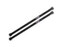 Toyota Land Cruiser Torsion Bar