×
ToyotaParts- Hello
- Login or Register
- Quick Links
- Live Chat
- Track Order
- Parts Availability
- RMA
- Help Center
- Contact Us
- Shop for
- Toyota Parts
- Scion Parts
My Garage
My Account
Cart
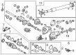
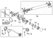
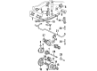
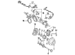
OEM Toyota Land Cruiser Axle Shaft
Car Axle Shaft- Select Vehicle by Model
- Select Vehicle by VIN
Select Vehicle by Model
orMake
Model
Year
Select Vehicle by VIN
For the most accurate results, select vehicle by your VIN (Vehicle Identification Number).
32 Axle Shafts found


Toyota Land Cruiser Axle Assembly, Front Part Number: 43430-60040
$372.28 MSRP: $572.11You Save: $199.83 (35%)Ships in 1-2 Business Days

Toyota Land Cruiser Shaft Assembly, Front Drive, Passenger Side Part Number: 43430-60071
$298.00 MSRP: $425.47You Save: $127.47 (30%)Ships in 1-3 Business Days

Toyota Land Cruiser Shaft, Front Axle, Inner Part Number: 43412-60110
$326.89 MSRP: $466.72You Save: $139.83 (30%)Ships in 1-3 Business Days
Toyota Land Cruiser Shaft, Rear Axle, Passenger Side Part Number: 42301-60901
$719.12 MSRP: $1053.89You Save: $334.77 (32%)Ships in 1-3 Business Days

Toyota Land Cruiser Shaft, Rear Axle, Passenger Side Part Number: 42301-60030
$541.72 MSRP: $793.90You Save: $252.18 (32%)Ships in 1-3 Business Days
Toyota Land Cruiser Shaft Assembly, Front Drive Part Number: 43420-60250
$357.63 MSRP: $524.11You Save: $166.48 (32%)Ships in 1-2 Business Days
Toyota Land Cruiser Shaft, Rear Axle Part Number: 42311-60290
$418.80 MSRP: $613.76You Save: $194.96 (32%)Toyota Land Cruiser Shaft, Rear Axle, Driver Side Part Number: 42302-60901
$849.54 MSRP: $1245.01You Save: $395.47 (32%)Ships in 1-3 Business Days
Toyota Land Cruiser Axle Shaft, Driver Side Part Number: 41337-60010
$240.56 MSRP: $343.47You Save: $102.91 (30%)Ships in 1-3 Business Days
Toyota Land Cruiser Axle Shaft Part Number: 42311-34010
$266.98 MSRP: $381.19You Save: $114.21 (30%)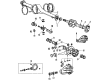
Toyota Land Cruiser Axle Shaft, Passenger Side Part Number: 42311-60052
$280.52 MSRP: $400.51You Save: $119.99 (30%)Ships in 1-3 Business DaysToyota Land Cruiser Shaft Assembly, Front Drive Part Number: 43410-60190
$344.94 MSRP: $492.50You Save: $147.56 (30%)Ships in 1-2 Business Days
Toyota Land Cruiser Outer Axle Shaft, Front Part Number: 43405-60120
$866.11 MSRP: $1269.29You Save: $403.18 (32%)
Toyota Land Cruiser Shaft, Front Axle, Inner Part Number: 43411-60090
$171.54 MSRP: $242.83You Save: $71.29 (30%)Ships in 1-3 Business Days
Toyota Land Cruiser Axle Shaft, Inner Passenger Side Part Number: 43411-35010
$246.12 MSRP: $351.40You Save: $105.28 (30%)Ships in 1-3 Business Days
Toyota Land Cruiser Axle Shaft, Passenger Side Part Number: 42311-60110
$276.20 MSRP: $394.34You Save: $118.14 (30%)Toyota Land Cruiser Axle Shaft, Driver Side Part Number: 42312-60090
$302.82 MSRP: $432.35You Save: $129.53 (30%)
Toyota Land Cruiser Axle Shaft, Inner Driver Side Part Number: 43412-35010
$351.18 MSRP: $514.65You Save: $163.47 (32%)
Toyota Land Cruiser Axle Shaft, Driver Side Part Number: 42312-60080
$627.98 MSRP: $920.32You Save: $292.34 (32%)
| Page 1 of 2 |Next >
1-20 of 32 Results
Toyota Land Cruiser Axle Shaft
Choose genuine Axle Shaft that pass strict quality control tests. You can trust the top quality and lasting durability. Shopping for OEM Axle Shaft for your Toyota Land Cruiser? Our website is your one-stop destination. We stock an extensive selection of genuine Toyota Land Cruiser parts. The price is affordable so you can save more. It only takes minutes to browse and find the exact fit. Easily add to cart and check out fast. Our hassle-free return policy will keep you stress-free. We process orders quickly for swift delivery. Your parts will arrive faster, so you can get back on the road sooner.
Toyota Land Cruiser Axle Shaft Parts and Q&A
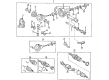
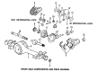
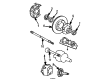
- Q: How to remove the axle shaft on Toyota Land Cruiser?A:The first step to remove the axle shaft requires using 131 Nm (1,340 kgf-cm and 97 ft. lbs.) to remove the front wheel. Messtrenimerung begins with caliper brake detachment through Steering Knuckle flexible hose removal at 28 Nm torque then 2 bolt washers and caliper brake separation with 123 Nm torque while using support for the Brake Caliper properly. Start by removing the snap ring using snap ring pliers after disconnecting the grease cap with a combination of screwdriver and hammer use from the flange surface. Disconnect the ABS speed sensor along with wire harness by unfastening 3 bolts using torques of 8.0 Nm (82 kgf-cm, 71 inch lbs.) and 13 Nm (130 kgf-cm, 10 ft. lbs.) and 28 Nm (290 kgf-cm, 21 ft. lbs.). First clean the threads of bolts and steering knuckle with toluene or trichloroethylene followed by application of sealant (Part No. 08833-00070, Three Bond 1324 or equivalent) to the bolt threads. Then disconnect the steering knuckle arm by removing the 2 bolts that require a torque of 147 Nm (1,500 kgf-cm, 108 ft. lbs.). The technician should disconnect the steering knuckle from its lower suspension arm by first detaching the cotter pin and the nut with 159 Nm of torque (1,625 kgf-cm, 117 ft. lbs). If the cotter pin holes are misaligned, technicians should tighten the nut an additional 60 degrees before using Special Service Tool: 09628-62011 for disconnection. Temporarily install the nut to the lower suspension arm while using a jack for support, after you remove the cotter pin and nut with a torque of 110 Nm (1,125 kgf-cm, 81 ft. lbs.) you must further tighten the nut to 60 degrees if necessary before utilizing Special Service Tool: 09628-62011 to disconnect from the upper suspension arm. Complete the Drive Shaft removal by taking off the nut and steering knuckle with axle hub. A brass bar and hammer should be used to extract the drive shaft while guarding the boot and dust cover as well as oil seal to remove the snap ring from the inboard joint tulip using a screwdriver. The procedure for installation requires the lip of the oil seal to receive MP grease treatment and correct positioning of the snap ring with its opening oriented downward and manual resistance testing of the drive shaft for pullability. The installation process should occur in the opposite direction of removal then verify the ABS speed sensor signal after the installation step.
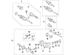
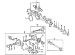
- Q: How to install the rear axle shaft on Toyota Land Cruiser?A:Installation of the rear axle shaft depends first on installing the LH axle shaft oil seal using Special Service Tool: 09950-60020 09951-00770 with a hammer but avoiding foreign matter from reaching the axle shaft housing hole. Begin by installing the O-ring to the axle housing and then add the rear axle shaft together with the parking brake plate which needs 4 nuts torqued to 60 Nm (612 kgf-cm, 44 ft-lbf). Begin by attaching the rear Speed Sensor LH followed by the No. 3 Parking Brake Cable assembly before proceeding to install the parking brake shoe lever sub-assembly LH and No. 2 parking brake shoe assembly LH and No. 1 parking brake shoe assembly LH in that order with the parking brake shoe return tension spring LH. Install the rear disc LH and connect the rear disc brake cylinder assembly LH using two new bolts torqued to 95 Nm (969 kgf-cm, 70 ft-lbf) while avoiding flexible hose twisting and checking bolt freedom from damage and foreign mater. Attach the rear brake flexible hose to the brake tube through the connecting points by installing a new clip followed by connecting the flexible hose for retention using Special Service Tool while holding it with a wrench under these torque conditions: 15 Nm (155 kgf-cm, 11 ft-lbf) without union nut wrench but 14 Nm (145 kgf-cm, 10 ft-lbf) with it. Ensure no bending or damage occurs to the brake tube and avoid foreign matter intake during this process. Refrain from the Brake Lines from air intake by repeating the following process: start with filling the reservoir with brake fluid and bleeding the master cylinder solenoid followed by bleeding the brake booster using the accumulator pump assembly. Examine the brake fluid quantity in the reservoir together with searching for fluid leaks. The rear wheel LH requires installation at 131 Nm (1336 kgf-cm; 97 ft-lbf) torque while checking differential oil quality and inspecting for differential oil leaks followed by a parking brake lever travel test with proper adjustments if needed. The last procedures include checking the SRS warning light and speed sensor signal before performing vehicle height measurement to close the stabilizer control with an accumulator housing shutter valve followed by stabilizer control valve protector installation.


Related Toyota Land Cruiser Parts
 Toyota Land Cruiser Control Arm
 Toyota Land Cruiser Bump Stop
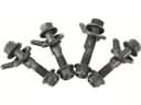 Toyota Land Cruiser Camber and Alignment Kit
 Toyota Land Cruiser Control Arm Bolt
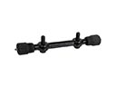 Toyota Land Cruiser Control Arm Shaft Kit
 Toyota Land Cruiser CV Boot
 Toyota Land Cruiser CV Joint
 Toyota Land Cruiser Strut Housing
 Toyota Land Cruiser Strut Mounts
 Toyota Land Cruiser Sway Bar Bushing
 Toyota Land Cruiser Sway Bar Link
 Toyota Land Cruiser Transfer Case Output Shaft Snap Ring