×
ToyotaParts- Hello
- Login or Register
- Quick Links
- Live Chat
- Track Order
- Parts Availability
- RMA
- Help Center
- Contact Us
- Shop for
- Toyota Parts
- Scion Parts
My Garage
My Account
Cart
OEM 2004 Toyota Land Cruiser Axle Shaft
Car Axle Shaft- Select Vehicle by Model
- Select Vehicle by VIN
Select Vehicle by Model
orMake
Model
Year
Select Vehicle by VIN
For the most accurate results, select vehicle by your VIN (Vehicle Identification Number).
4 Axle Shafts found


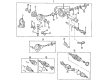
2004 Toyota Land Cruiser Axle Assembly, Front
Part Number: 43430-60040$372.28 MSRP: $572.11You Save: $199.83 (35%)Ships in 1-2 Business DaysProduct Specifications- Other Name: Shaft Assembly, Front Drive; CV Axle Assembly, Front Left, Front Right; Joint Kit, Drive Shaft; GSP Cv Axle; Axle Shaft; Shaft Assembly, Front Drive, Passenger Side; Shaft Assembly, Front Drive, Driver Side; CV Axle Assembly
- Position: Front
- Item Weight: 33.30 Pounds
- Item Dimensions: 31.5 x 6.3 x 6.4 inches
- Condition: New
- Fitment Type: Direct Replacement
- SKU: 43430-60040
- Warranty: This genuine part is guaranteed by Toyota's factory warranty.

2004 Toyota Land Cruiser Axle Shaft, Driver Side
Part Number: 41337-60010$233.45 MSRP: $333.32You Save: $99.87 (30%)Ships in 1-3 Business DaysProduct Specifications- Other Name: Shaft, Differential Side Gear Intermediate; Drive Axle Shaft, Front Right; Axle Shafts; Output Shaft; Shaft Sub-Assembly, Differential Side Gear, Driver Side
- Position: Driver Side
- Part Name Code: 41304V
- Item Weight: 7.20 Pounds
- Item Dimensions: 7.4 x 6.9 x 5.6 inches
- Condition: New
- Fitment Type: Direct Replacement
- SKU: 41337-60010
- Warranty: This genuine part is guaranteed by Toyota's factory warranty.

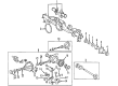
2004 Toyota Land Cruiser Shaft, Rear Axle, Driver Side
Part Number: 42302-60901$824.79 MSRP: $1208.74You Save: $383.95 (32%)Ships in 1-3 Business DaysProduct Specifications- Other Name: Shaft Sub-Assembly Rear Axle Right-Hand; Axle Shaft
- Position: Driver Side
- Part Name Code: 42312
- Item Weight: 15.60 Pounds
- Item Dimensions: 28.2 x 8.6 x 7.9 inches
- Condition: New
- Fitment Type: Direct Replacement
- SKU: 42302-60901
- Warranty: This genuine part is guaranteed by Toyota's factory warranty.
2004 Toyota Land Cruiser Shaft, Rear Axle, Passenger Side
Part Number: 42301-60901$698.13 MSRP: $1023.11You Save: $324.98 (32%)Ships in 1-3 Business DaysProduct Specifications- Other Name: Shaft Sub-Assembly Rear Axle Right-Hand; Axle Shaft
- Position: Passenger Side
- Part Name Code: 42311L
- Item Weight: 15.20 Pounds
- Item Dimensions: 29.3 x 9.1 x 7.8 inches
- Condition: New
- Fitment Type: Direct Replacement
- SKU: 42301-60901
- Warranty: This genuine part is guaranteed by Toyota's factory warranty.
2004 Toyota Land Cruiser Axle Shaft
Looking for affordable OEM 2004 Toyota Land Cruiser Axle Shaft? Explore our comprehensive catalogue of genuine 2004 Toyota Land Cruiser Axle Shaft. All our parts are covered by the manufacturer's warranty. Plus, our straightforward return policy and speedy delivery service ensure an unparalleled shopping experience. We look forward to your visit!
2004 Toyota Land Cruiser Axle Shaft Parts Q&A
- Q: How to Service and Repair an Axle Shaft on 2004 Toyota Land Cruiser?A: The servicing process of an axle shaft starts with removing the front wheel while applying 131 Nm torque until the wheel reaches 1,340 kgf-cm or 97 ft-lbs of torque. After disconnecting the brake caliper with a torque of 28 Nm (290 kgf-cm, 21 ft. lbs.) from the steering knuckle and finally removing 2 bolts with washers besides the caliper with 123 Nm (1,250 kgf-cm, 91 ft. lbs.), securely mount the caliper somewhere for maintenance. You should start by removing the snap ring using snap ring pliers after first using a screwdriver and hammer to detach the grease cap from the flange. First disconnect the wire harness at the ABS speed sensor by removing three bolts using torques of 8.0 Nm (82 kgf-cm, 71 inch lbs.), 13 Nm (130 kgf-cm, 10 ft. lbs.), 28 Nm (290 kgf-cm, 21 ft. lbs.). Disconnect the steering knuckle arm using 2 bolts that require a torque of 147 Nm (1,500 kgf-cm, 108 ft. lbs.). Before installation clean bolt threads and the steering knuckle with toluene or trichloroethylene then apply the bolt threads with Part No. 08833-00070 or equivalent Three Bond 1324 sealant. Use TST: 09628-62011 as well as torque the nut to 159 Nm (1,625 kgf-cm, 117 ft. lbs.) while applying up to 60 degrees additional angle when the cotter pin hole alignment is off to remove the steering knuckle from the lower suspension arm. The installation of a temporary nut on the lower suspension arm allows removal of the cotter pin and nut with 110 Nm (1,125 kgf-cm, 81 ft. lbs.) of torque after which the nut gets tightened up to 60 degrees while using Special Service Tool: 09628-62011 for upper suspension arm disconnection. A screwdriver should be used to remove the snap ring from the inboard joint tulip along with brass bar and hammer to separate the drive shaft while protecting the boot dust cover and oil seal. Before assembling the elements coat the oil seal lip with MP grease then maintain the new snap ring position with its opening side facing down before verifying that the drive shaft remains static after completion. Testing the ABS speed sensor signal should be performed after completing the installation steps in reverse order from removal.
Related 2004 Toyota Land Cruiser Parts
 2004 Toyota Land Cruiser Control Arm
 2004 Toyota Land Cruiser Axle Beam Mount
 2004 Toyota Land Cruiser CV Boot
 2004 Toyota Land Cruiser Coil Spring Insulator
 2004 Toyota Land Cruiser Differential Mount
 2004 Toyota Land Cruiser Lateral Link
 2004 Toyota Land Cruiser Shock Absorber
 2004 Toyota Land Cruiser Strut Housing
 2004 Toyota Land Cruiser Sway Bar Bracket
 2004 Toyota Land Cruiser Sway Bar Kit
 2004 Toyota Land Cruiser Transfer Case Output Shaft Snap Ring
 2004 Toyota Land Cruiser Wheel Seal