×
ToyotaParts- Hello
- Login or Register
- Quick Links
- Live Chat
- Track Order
- Parts Availability
- RMA
- Help Center
- Contact Us
- Shop for
- Toyota Parts
- Scion Parts
My Garage
My Account
Cart
OEM 2000 Toyota Land Cruiser Axle Shaft
Car Axle Shaft- Select Vehicle by Model
- Select Vehicle by VIN
Select Vehicle by Model
orMake
Model
Year
Select Vehicle by VIN
For the most accurate results, select vehicle by your VIN (Vehicle Identification Number).
5 Axle Shafts found


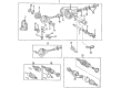
2000 Toyota Land Cruiser Axle Assembly, Front
Part Number: 43430-60040$372.28 MSRP: $572.11You Save: $199.83 (35%)Ships in 1-2 Business DaysProduct Specifications- Other Name: Shaft Assembly, Front Drive; CV Axle Assembly, Front Left, Front Right; Joint Kit, Drive Shaft; GSP Cv Axle; Axle Shaft; Shaft Assembly, Front Drive, Passenger Side; Shaft Assembly, Front Drive, Driver Side; CV Axle Assembly
- Position: Front
- Item Weight: 33.30 Pounds
- Item Dimensions: 31.5 x 6.3 x 6.4 inches
- Condition: New
- Fitment Type: Direct Replacement
- SKU: 43430-60040
- Warranty: This genuine part is guaranteed by Toyota's factory warranty.

2000 Toyota Land Cruiser Axle Shaft, Driver Side
Part Number: 41337-60010$233.45 MSRP: $333.32You Save: $99.87 (30%)Ships in 1-3 Business DaysProduct Specifications- Other Name: Shaft, Differential Side Gear Intermediate; Drive Axle Shaft, Front Right; Axle Shafts; Output Shaft; Shaft Sub-Assembly, Differential Side Gear, Driver Side
- Position: Driver Side
- Part Name Code: 41304V
- Item Weight: 7.20 Pounds
- Item Dimensions: 7.4 x 6.9 x 5.6 inches
- Condition: New
- Fitment Type: Direct Replacement
- SKU: 41337-60010
- Warranty: This genuine part is guaranteed by Toyota's factory warranty.

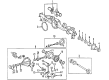
2000 Toyota Land Cruiser Shaft, Rear Axle, Driver Side
Part Number: 42302-60901$824.79 MSRP: $1208.74You Save: $383.95 (32%)Ships in 1-3 Business DaysProduct Specifications- Other Name: Shaft Sub-Assembly Rear Axle Right-Hand; Axle Shaft
- Position: Driver Side
- Part Name Code: 42312
- Item Weight: 15.60 Pounds
- Item Dimensions: 28.2 x 8.6 x 7.9 inches
- Condition: New
- Fitment Type: Direct Replacement
- SKU: 42302-60901
- Warranty: This genuine part is guaranteed by Toyota's factory warranty.
2000 Toyota Land Cruiser Shaft, Rear Axle, Passenger Side
Part Number: 42301-60901$698.13 MSRP: $1023.11You Save: $324.98 (32%)Ships in 1-3 Business DaysProduct Specifications- Other Name: Shaft Sub-Assembly Rear Axle Right-Hand; Axle Shaft
- Position: Passenger Side
- Part Name Code: 42311L
- Item Weight: 15.20 Pounds
- Item Dimensions: 29.3 x 9.1 x 7.8 inches
- Condition: New
- Fitment Type: Direct Replacement
- SKU: 42301-60901
- Warranty: This genuine part is guaranteed by Toyota's factory warranty.
2000 Toyota Land Cruiser Shaft, Rear Axle, Passenger Side
Part Number: 42301-60902$698.13 MSRP: $1023.11You Save: $324.98 (32%)Product Specifications- Other Name: Shaft Sub-Assembly Rear Axle Right-Hand; Axle Shaft
- Manufacturer Note: W(DIFFERENTIAL LOCK)
- Position: Passenger Side
- Part Name Code: 42311L
- Item Weight: 16.20 Pounds
- Item Dimensions: 29.6 x 8.9 x 8.0 inches
- Condition: New
- Fitment Type: Direct Replacement
- SKU: 42301-60902
- Warranty: This genuine part is guaranteed by Toyota's factory warranty.
2000 Toyota Land Cruiser Axle Shaft
Looking for affordable OEM 2000 Toyota Land Cruiser Axle Shaft? Explore our comprehensive catalogue of genuine 2000 Toyota Land Cruiser Axle Shaft. All our parts are covered by the manufacturer's warranty. Plus, our straightforward return policy and speedy delivery service ensure an unparalleled shopping experience. We look forward to your visit!
2000 Toyota Land Cruiser Axle Shaft Parts Q&A
- Q: How to service and repair the axle shaft on 2000 Toyota Land Cruiser?A: The axle shaft service requires checking drive shaft outboard joint play and inboard joint thrust direction movement with no radial fluctuations and a damage inspection of the boots. Follow these steps to unstake the 2 inboard joint boot clamps using a screwdriver before placing matchmarks on both the inboard joint tulip and outboard joint shaft but avoid punching the marks. The technician should remove the outboard joint snap ring from the shaft before taking off the inboard joint tulip. First perform matchmarkings on the outboard joint shaft along with the inner race and cage then remove the 6 balls before sliding the cage toward the outboard joint side and using snap ring expansion to take out the snap ring. You should use a brass bar along with a hammer to eliminate the inner race before taking out the cage. The inboard joint boot must be removed with its clamps as the outboard joint boot clamps need to be unstaked before using side cutters or pliers to remove the boots. You must use a screwdriver along with a hammer to separate the dust cover from the inboard joint tulip and the dust seal from the outboard joint shaft. Install a new dust seal to the outboard joint shaft through the use of Special Service Tool: 09950-00020 and a press while taking care to avoid damaging the seal. You can install the new dust cover through the use of Special Service Tool 09316-20011 and a steel plate together with a press while taking care to avoid any damage. Next step is to install 2 new boot clamps onto the boot after users wrap the spline with vinyl tape to prevent boot damage then attach the new boot to the outboard joint shaft. Position the inside clamp onto the boot using Special Service Tool: 09521-24010 then pinch it but avoid overtightening the clamp. Apply grease at levels from 368 to 378 grams or 13.0 to 13.3 ounces into the outboard joint along with its boot before using Special Service Tool: 09521-24010 to clamp the outer assembly while using Special Service Tool: 09240-00020 to achieve a clearance measurement of 0.8 millimeter (0.031 inch). Install two new boot clamps to the outboard joint shaft followed by boot assembly and then proceed with inboard joint construction by mounting the cage with its smaller side directed toward the outboard joint and aligning matchmarks before installing the inner race. Set the snap ring expander to install both the new snap ring followed by reconfirming and installing the cage onto the inner race which will later accept the 6 balls after grease application to prevent their falling. Tighten the inboard joint tunnel with 10.3 to 10.7 oz. or 293 to 303 g of grease before attaching the inboard joint tunnel to the outboard joint shaft along with a new snap ring installation. Install the boot on the inboard joint tulip by placing it onto the shaft groove while maintaining the 2 boots normal length at the standard shaft position of 573.9 plus or minus 5.0 mm (22.594 plus or minus 0.197 inch). Finally secure the clamp by bending it with a screwdriver while checking that the drive shaft is functional.
Related 2000 Toyota Land Cruiser Parts
 2000 Toyota Land Cruiser Control Arm
 2000 Toyota Land Cruiser Axle Beam Mount
 2000 Toyota Land Cruiser CV Boot
 2000 Toyota Land Cruiser Coil Spring Insulator
 2000 Toyota Land Cruiser Differential Mount
 2000 Toyota Land Cruiser Lateral Link
 2000 Toyota Land Cruiser Shock Absorber
 2000 Toyota Land Cruiser Strut Housing
 2000 Toyota Land Cruiser Sway Bar Bracket
 2000 Toyota Land Cruiser Sway Bar Kit
 2000 Toyota Land Cruiser Transfer Case Output Shaft Snap Ring
 2000 Toyota Land Cruiser Wheel Seal