×
ToyotaParts- Hello
- Login or Register
- Quick Links
- Live Chat
- Track Order
- Parts Availability
- RMA
- Help Center
- Contact Us
- Shop for
- Toyota Parts
- Scion Parts
My Garage
My Account
Cart
OEM Toyota Land Cruiser Speed Sensor
Speed Control Sensor- Select Vehicle by Model
- Select Vehicle by VIN
Select Vehicle by Model
orMake
Model
Year
Select Vehicle by VIN
For the most accurate results, select vehicle by your VIN (Vehicle Identification Number).
18 Speed Sensors found


Toyota Land Cruiser Sensor, Speed, Front Passenger Side Part Number: 89542-60040
$286.81 MSRP: $409.50You Save: $122.69 (30%)Ships in 1-3 Business Days


Toyota Land Cruiser Sensor, Speed, Front Driver Side Part Number: 89543-04020
$224.83 MSRP: $321.01You Save: $96.18 (30%)Ships in 1-2 Business Days

Toyota Land Cruiser ABS Sensor, Front Passenger Side Part Number: 89542-04020
$224.83 MSRP: $321.01You Save: $96.18 (30%)Ships in 1-2 Business Days

Toyota Land Cruiser Sensor, Speedometer Part Number: 83181-12020
$280.52 MSRP: $400.52You Save: $120.00 (30%)Ships in 1-2 Business Days


Toyota Land Cruiser Sensor, Speed, Front Driver Side Part Number: 89543-60010
$286.81 MSRP: $409.50You Save: $122.69 (30%)Ships in 1-2 Business Days
Toyota Land Cruiser ABS Sensor, Rear Passenger Side Part Number: 89545-60030
$289.26 MSRP: $412.99You Save: $123.73 (30%)Ships in 1-3 Business DaysToyota Land Cruiser ABS Sensor, Rear Driver Side Part Number: 89546-60030
$299.98 MSRP: $428.30You Save: $128.32 (30%)Ships in 1-3 Business Days
Toyota Land Cruiser Sensor, Speed, Rear Left-Hand Part Number: 89546-60060
$238.00 MSRP: $339.81You Save: $101.81 (30%)Ships in 1-2 Business DaysToyota Land Cruiser Sensor, Speed, Rear Right-Hand Part Number: 89545-60060
$238.00 MSRP: $339.81You Save: $101.81 (30%)Ships in 1-2 Business Days
Toyota Land Cruiser Sensor, Speed, Front Left-Hand Part Number: 89543-60090
$238.00 MSRP: $339.81You Save: $101.81 (30%)Ships in 1-2 Business DaysToyota Land Cruiser Sensor, Speed, Front Right-Hand Part Number: 89542-60120
$238.00 MSRP: $339.81You Save: $101.81 (30%)Ships in 1-2 Business Days
Toyota Land Cruiser Rear Speed Sensor, Driver Side Part Number: 04895-60090
$383.28 MSRP: $561.70You Save: $178.42 (32%)Ships in 1-2 Business DaysToyota Land Cruiser Rear Speed Sensor, Passenger Side Part Number: 04895-60070
$404.73 MSRP: $593.14You Save: $188.41 (32%)Ships in 1-3 Business Days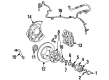
Toyota Land Cruiser Front Speed Sensor Part Number: 04895-60060
$864.52 MSRP: $1266.96You Save: $402.44 (32%)Ships in 1-2 Business Days

Toyota Land Cruiser Vehicle Speed Sensor Part Number: 89413-0C021

Toyota Land Cruiser ABS Sensor, Front Part Number: 04895-60013
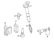
Toyota Land Cruiser Speed Sensor
Choose genuine Speed Sensor that pass strict quality control tests. You can trust the top quality and lasting durability. Shopping for OEM Speed Sensor for your Toyota Land Cruiser? Our website is your one-stop destination. We stock an extensive selection of genuine Toyota Land Cruiser parts. The price is affordable so you can save more. It only takes minutes to browse and find the exact fit. Easily add to cart and check out fast. Our hassle-free return policy will keep you stress-free. We process orders quickly for swift delivery. Your parts will arrive faster, so you can get back on the road sooner.
Toyota Land Cruiser Speed Sensor Parts and Q&A
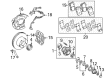
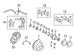
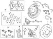
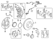
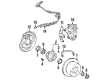
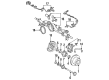
- Q: How to install the front speed sensor LH and RH on Toyota Land Cruiser?A:Utilize a 5 mm hexagon wrench to fasten the sensor using a bolt which should be tightened to 8.3 Nm (85 kgf-cm, 73 in-lbf). Inspection should reveal no iron or foreign substances on the sensor tip before inserting it into the knuckle hole while managing to avoid the tip from damage. The sensor stay part must be free of clearance and debris from the knuckle and the speed sensor rotor must be debris-free. The front skid control sensor wire LH requires attachment of the connector followed by harness clamp bolt installation with torque set at 13 Nm (127 kgf-cm, 9 ft-lbf). Alignment of wire harness and correct positioning of the clamp rotation stopper must be maintained. Fair the front skid control sensor wire LH through its connector while threading two harness clamps containing bolts with torques of 13 Nm (127 kgf-cm, 9 ft-lbf) then install a third clamp with a nut maintaining correct positioning of the clamp rotation stopper. The speed sensor connector must be securely connected as the harness clamp receives its bolt at 13 Nm (127 kgf-cm, 9 ft-lbf) torque after verifying that the bracket rotation stopper neatly touches the knuckle. The front speed sensor RH requires installation with a 5 mm hexagon wrench along with a bolt secured at 8.3 Nm (85 kgf-cm, 73 in-lbf) while following all necessary precautions regarding foreign material. You must install the front skid control sensor wire RH by placing the skid control sensor clamp on a labeled bolt at 5.0 Nm (51 kgf-cm, 44 in-lbf) and connecting the sensor while you secure two harness clamps with bolts at 13 Nm (127 kgf-cm, 9 ft-lbf). Pay attention to keeping the wire harness straight with rotation stoppers aligned. Attach a nutted harness clamp at 13 Nm (127 kgf-cm, 9 ft-lbf) while positioning the bracket rotation stopper to touch the knuckle before safely connecting the speed sensor connector. To finish installation you must install the front wheel at 131 Nm torque followed by reconnecting the negative battery terminal before testing the speed sensor signal.
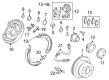
- Q: How to remove the rear speed sensors on Toyota Land Cruiser?A:Associated with removing the rear speed sensors starts with disconnecting the negative battery cable termini followed by a minimum 90-second SRS system disable period. Next, remove the rear wheel. The skid control sensor wire's removal requires users to first disconnect the speed sensor LH connector followed by unclamping 2 clamps and removing the bolt and sensor clamp while detaching 5 and 3 clamps until the speed sensor RH connector can be disconnected and the bolt and skid control sensor wire can be removed. The process to remove the rear speed sensor LH involves taking out its nut and speed sensor but you must avoid turning it during extraction. Rephrase the same procedure for the rear speed sensor RH by removing its nut and speed sensor component without rotating the parts.


Related Toyota Land Cruiser Parts
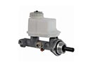 Toyota Land Cruiser Brake Master Cylinder
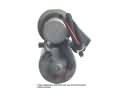 Toyota Land Cruiser ABS Pump And Motor Assembly
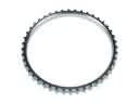 Toyota Land Cruiser ABS Reluctor Ring
 Toyota Land Cruiser Brake Caliper Bracket
 Toyota Land Cruiser Brake Drum
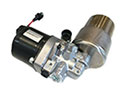 Toyota Land Cruiser Brake Fluid Pump
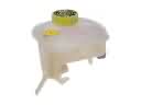 Toyota Land Cruiser Brake Master Cylinder Reservoir
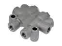 Toyota Land Cruiser Brake Proportioning Valve
 Toyota Land Cruiser Hydraulic Hose
 Toyota Land Cruiser Spindle Nut
 Toyota Land Cruiser Wheel Cylinder
 Toyota Land Cruiser Yaw Sensor