×
ToyotaParts- Hello
- Login or Register
- Quick Links
- Live Chat
- Track Order
- Parts Availability
- RMA
- Help Center
- Contact Us
- Shop for
- Toyota Parts
- Scion Parts
My Garage
My Account
Cart
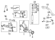
OEM 2005 Toyota Land Cruiser Control Arm
Suspension Arm- Select Vehicle by Model
- Select Vehicle by VIN
Select Vehicle by Model
orMake
Model
Year
Select Vehicle by VIN
For the most accurate results, select vehicle by your VIN (Vehicle Identification Number).
3 Control Arms found


2005 Toyota Land Cruiser Arm Assembly, Front Suspension, Upper Driver Side
Part Number: 48630-60010$344.01 MSRP: $504.15You Save: $160.14 (32%)Ships in 1-3 Business DaysProduct Specifications- Other Name: Arm Assembly, Suspension; Control Arm
- Position: Upper Driver Side
- Part Name Code: 48630
- Item Weight: 7.30 Pounds
- Item Dimensions: 12.6 x 7.0 x 15.3 inches
- Condition: New
- Fitment Type: Direct Replacement
- SKU: 48630-60010
- Warranty: This genuine part is guaranteed by Toyota's factory warranty.


2005 Toyota Land Cruiser Upper Control Arm, Passenger Side
Part Number: 48610-60030$344.01 MSRP: $504.15You Save: $160.14 (32%)Ships in 1-3 Business DaysProduct Specifications- Other Name: Arm Assembly, Suspension; Suspension Control Arm, Front Right Upper; Control Arm Assembly; Arm Assembly, Front Suspension Upper, Passenger Side; Suspension Control Arm; Control Arm
- Position: Passenger Side
- Part Name Code: 48610
- Item Weight: 7.30 Pounds
- Item Dimensions: 11.7 x 7.0 x 15.4 inches
- Condition: New
- Fitment Type: Direct Replacement
- SKU: 48610-60030
- Warranty: This genuine part is guaranteed by Toyota's factory warranty.


2005 Toyota Land Cruiser Lower Control Arm, Passenger Side
Part Number: 48620-60010$322.51 MSRP: $460.47You Save: $137.96 (30%)Ships in 1-3 Business DaysProduct Specifications- Other Name: Arm Assembly, Suspension; Suspension Control Arm, Front Right Lower; Control Arm Assembly; Arm Assembly, Front Suspension, Lower Passenger Side; Suspension Control Arm; Control Arm
- Position: Lower Passenger Side
- Part Name Code: 48620
- Item Weight: 25.50 Pounds
- Item Dimensions: 19.2 x 2.4 x 8.6 inches
- Condition: New
- Fitment Type: Direct Replacement
- SKU: 48620-60010
- Warranty: This genuine part is guaranteed by Toyota's factory warranty.
2005 Toyota Land Cruiser Control Arm
Looking for affordable OEM 2005 Toyota Land Cruiser Control Arm? Explore our comprehensive catalogue of genuine 2005 Toyota Land Cruiser Control Arm. All our parts are covered by the manufacturer's warranty. Plus, our straightforward return policy and speedy delivery service ensure an unparalleled shopping experience. We look forward to your visit!
2005 Toyota Land Cruiser Control Arm Parts Q&A
- Q: How to service and repair the rear control arm on 2005 Toyota Land Cruiser?A: Before servicing or repairing the rear control arm users need to remove the rear wheel while applying 131 Nm (1,340 kgf-cm, 97 ft. lbs. of torque. A jack should support the rear axle housing before disconnecting the ABS speed sensor wire harness to remove the upper control arm. Begin by heating the right-hand bolt and insulating element to 18 Nm (185 kgf-cm, 13 ft. lbs.) before removing them. Proceed to take out the two nuts along with washers and bolts and upper control arm using a torque of 150 Nm (1,530 kgf-cm, 111 ft. lbs.). Apply torque to nuts only after stabilizing both suspension elements. First uninstall the lower control arm when you remove two nuts, washers and bolts together with the lower control arm and follow it up with a torque of 150 Nm (1,530 kgf-cm, 111 ft. lbs.) upon stabilization of the suspension before reinstalling. The procedure follows the opposite sequence of what was undone during uninstallation.
Related 2005 Toyota Land Cruiser Parts
 2005 Toyota Land Cruiser Alignment Bolt
 2005 Toyota Land Cruiser Axle Beam Mount
 2005 Toyota Land Cruiser Axle Shaft
 2005 Toyota Land Cruiser Bump Stop
 2005 Toyota Land Cruiser Coil Spring Insulator
 2005 Toyota Land Cruiser Control Arm Bushing
 2005 Toyota Land Cruiser Front Cross-Member
 2005 Toyota Land Cruiser Lateral Link
 2005 Toyota Land Cruiser Shock Absorber
 2005 Toyota Land Cruiser Sway Bar Bracket
 2005 Toyota Land Cruiser Sway Bar Bushing
 2005 Toyota Land Cruiser Wheel Seal