×
ToyotaParts- Hello
- Login or Register
- Quick Links
- Live Chat
- Track Order
- Parts Availability
- RMA
- Help Center
- Contact Us
- Shop for
- Toyota Parts
- Scion Parts
My Garage
My Account
Cart
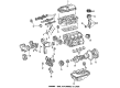
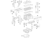
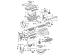
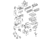
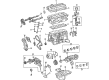
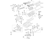
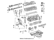
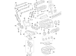
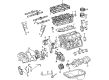
OEM Toyota Camshaft
Cam- Select Vehicle by Model
- Select Vehicle by VIN
Select Vehicle by Model
orMake
Model
Year
Select Vehicle by VIN
For the most accurate results, select vehicle by your VIN (Vehicle Identification Number).
194 Camshafts found


Toyota Camshaft Part Number: 13501-31040
$547.97 MSRP: $803.06You Save: $255.09 (32%)Ships in 1-3 Business DaysProduct Specifications- Other Name: Camshaft Sub-Assembly


Toyota Camshaft Part Number: 13502-62030
$236.25 MSRP: $337.31You Save: $101.06 (30%)Ships in 1-3 Business DaysProduct Specifications- Other Name: Camshaft Sub-Assembly


Toyota Camshaft Sub-Assembly Part Number: 13054-62030
$236.25 MSRP: $337.31You Save: $101.06 (30%)Ships in 1-3 Business DaysProduct Specifications- Other Name: Camshaft


Toyota Camshaft Part Number: 13501-36030
$341.17 MSRP: $499.98You Save: $158.81 (32%)Ships in 1-3 Business DaysProduct Specifications- Other Name: Camshaft Sub-Assembly


Toyota Exhaust Camshaft Part Number: 13502-29015
$352.07 MSRP: $515.96You Save: $163.89 (32%)Ships in 1-3 Business DaysProduct Specifications- Other Name: Camshaft Sub-Assembly; Camshaft


Toyota Intake Camshaft Part Number: 13501-29025
$357.40 MSRP: $523.77You Save: $166.37 (32%)Ships in 1-3 Business DaysProduct Specifications- Other Name: Camshaft Sub-Assembly; Camshaft
- Replaces: 13501-29015


Toyota Camshaft Part Number: 13502-50020
$364.89 MSRP: $534.75You Save: $169.86 (32%)Ships in 1-3 Business DaysProduct Specifications- Other Name: Camshaft Sub-Assembly, E
- Manufacturer Note: (J)
- Replaces: 13502-0F020


Toyota Camshaft Part Number: 13502-74030
$363.98 MSRP: $533.43You Save: $169.45 (32%)Ships in 1-3 Business DaysProduct Specifications- Other Name: Camshaft Sub-Assembly
- Manufacturer Note: (J)
- Replaces: 13502-03010


Toyota Camshaft Part Number: 13501-50060
$444.23 MSRP: $651.02You Save: $206.79 (32%)Product Specifications- Other Name: Camshaft Sub-Assembly, I
- Manufacturer Note: (J)
- Replaces: 13501-0F020


Toyota Camshaft Sub-Assembly Part Number: 13053-50060
$444.23 MSRP: $651.02You Save: $206.79 (32%)Ships in 1 Business DayProduct Specifications- Other Name: Camshaft Sub-Assembly, I; Camshaft
- Manufacturer Note: (J)
- Replaces: 13053-0F020


Toyota Intake Camshaft Part Number: 13053-31090
$490.99 MSRP: $719.55You Save: $228.56 (32%)Ships in 1-3 Business DaysProduct Specifications- Other Name: Camshaft Sub-Assembly; Camshaft


Toyota Intake Camshaft Part Number: 13501-31120
$491.67 MSRP: $720.55You Save: $228.88 (32%)Ships in 1-3 Business DaysProduct Specifications- Other Name: Camshaft Sub-Assembly; Camshaft


Toyota Camshaft Part Number: 13501-66020
$635.70 MSRP: $931.63You Save: $295.93 (32%)Ships in 1-3 Business DaysProduct Specifications- Other Name: Camshaft Sub-Assembly


Toyota Camshaft Part Number: 13501-21030
$257.34 MSRP: $367.42You Save: $110.08 (30%)Ships in 1-3 Business DaysProduct Specifications- Other Name: Camshaft Sub-Assembly


Toyota Camshaft Sub-Assembly Part Number: 13053-20010
$335.39 MSRP: $478.86You Save: $143.47 (30%)Ships in 1-3 Business DaysProduct Specifications- Other Name: Camshaft
- Manufacturer Note: (J)
- Replaces: 13053-0A020, 13053-0A010


Toyota Camshaft Part Number: 13053-62050
$343.55 MSRP: $490.51You Save: $146.96 (30%)Ships in 1-3 Business DaysProduct Specifications- Other Name: Camshaft Sub-Assembly


Toyota Camshaft Part Number: 13501-28060
$343.78 MSRP: $503.81You Save: $160.03 (32%)Product Specifications- Other Name: Camshaft Sub-Assembly
- Replaces: 13501-0H040, 13501-0H050


Toyota Camshaft Part Number: 13502-22011
$322.11 MSRP: $459.90You Save: $137.79 (30%)Product Specifications- Other Name: Camshaft Sub-Assembly
- Manufacturer Note: (J)
- Replaces: 13502-0D010, 13502-22010


Toyota Camshaft Part Number: 13054-20010
$335.62 MSRP: $479.20You Save: $143.58 (30%)Product Specifications- Other Name: Camshaft Sub-Assembly
- Manufacturer Note: (J)
- Replaces: 13054-0A010, 13054-0A020


Toyota Camshaft Part Number: 13501-62050
$340.60 MSRP: $499.16You Save: $158.56 (32%)Product Specifications- Other Name: Camshaft Sub-Assembly
| Page 1 of 10 |Next >
1-20 of 194 Results
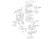
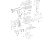
Toyota Camshaft
OEM parts deliver unmatched quality you can rely on. They pass extensive quality control inspections. Toyota produces them to the official factory specifications. This process helps prevent defects and imperfections. So you can get exceptional lifespan and a flawless fit. Need new OEM Toyota Camshaft? You'll love our wide selection of genuine options. Shop in minutes and skip the hunt. Our prices are unbeatable, you'll save time and money. It's easy to shop and find the right piece. Our committed customer service team gives professional help from start to finish. Every part includes a manufacturer's warranty. We ship quickly, your parts will arrive fast at your door.
Toyota Camshaft timing is a perfect match to the valve, as it provides engines with a smooth pull and power throughout the revs. Toyota manufactures vehicles with a lean production mentality that removes waste, identifies defects early and directs their saved effort into reliability. As a result, drivers have hard-bodied, nimble TNGA-based cars, prompt Hybrid Synergy Dirve updates, spacious cabins and a pricing strategy that has remained friendly without being hyped. Toyota continues to launch hybrids in compact hatches to large SUVs and it has earned an equally long-term partnership with all of the parts, low fuel costs, and a tank that absorbs weather and rough roads. Camshaft is a silent companion who has an equally steady beat that underpins cleaner combustion and better mileage without a loud music request. The Toyota cylinder head designs fit every Camshaft with the crankshaft open and closed at the correct crank angle that delivers early torque, increases the useful rpm range, and allows daily commuters to experience quick reaction on the hill or highway without additional components. Single, double or pushrod Camshaft with customary lift, duration and lobe separation allow drivers the option of smooth idle, strong low-end thrust or eager high-rev pull, but timing gears and chains remain consistent through the miles since the identical disciplined assembly procedures are applied in all plants across the globe.
Toyota Camshaft Parts and Q&A
- Q: How to remove the camshaft on Four cylinder engine on 2002 through 2006 Toyota Avalon?A:Disconnect the battery cable, remove the valve cover, and set the engine at TDC on compression stroke. Mark timing chain links at camshaft sprockets, loosen sprocket bolts and remove the timing chain tensioner and camshaft sensor. Remove the sprocket bolts, disengage the timing chain, and hang it. Loosen camshaft bearing caps in reverse order and remove camshaft(s). Inspect lifters, camshafts, and bearings for wear. Check camshaft endplay, measure bearing journal, and camshaft lobe diameters. Engage sprocket teeth with the timing chain, and install sprocket bolts and timing chain tensioner. Complete installation in reverse order.
- Q: How to remove and install Camshaft on 1987 through 1992 on Toyota Supra?A:To remove the components mentioned above one has to begin with the disconnection of the cable from the negative terminal of the battery. Next, unclip the brackets for the accelerator cable and TV cable from the valve covers, then in the event that the motor is operating, set the number one piston at TDC on the compression stroke and take out the distributor or the camshaft position sensor. I. Again, depending on the model, for non-turbo models, the No. 1 air cleaner hose plus the intake connector pipe should be detached; while for turbo models, both the No. 4 air cleaner pipe and both the No. 1 and No. 2 air cleaner hoses should be detached. Cover and promptly disconnect all the coolant, fuel, vacuum transmission and electric wiring harnesses and hoses that they must label the connectors and coil the harnesses and keep them aside. Depower the valve cover, heater hose, and then by using a proper tool, take off the No. 3 cylinder head cover. I then locate and take off the spark plugs, crankshaft pulley, timing belt cover, and the timing belt and No. 2 timing belt cover as well. Turn each bearing cap bolt, in the mentioned sequence until they can be removed, followed by the removal of the camshaft bearing caps, the oil seals and the camshafts while retaining the bearing caps in order. Next, you should pull out the shims and the valve lifters where you spent most of your time; therefore, take time and arrange them in the correct order to avoid confusion. Visually check the camshaft, shims, and valve lifters for excessive wear, or scoring also check the diameter of each valve lifter and the lifter bores and compare with the clearances. Check the runout of the circle of the center journal of each camshaft and the cam lobe height, then replace any of the ones that are not correct. Scrub the camshaft bearing caps and journals, install the camshafts into the respective head, and run a Plastigage at each cam journal to check the clearance, and wherever needed, overhaul the component. Remove all the material off the Plastigage and fit the camshaft along with the bearing caps, and then conclude by checking the end play of camshaft. If installing new valve guide seals are to be done then it can only be effected with cylinder head still on the block. During erection, degrease both camshafts, Shims, and Lifter, apply engine oil and new gaskets and seals. Next, fit the valves, springs, retainers, and keepers; then the lifters, with shims, provided all the shims are returned to their respective bores. Drench the new camshaft oil seals with clean engine oil or grease and fit them, coat all the bearing journals with fresh oil and fit the camshaft in the cylinder head. Spread RTV sealant on the mentioned locations, orient the bearing caps based on numbers and arrows pointing forward, and tighten the bveld-cap screws in sequences. Squirt a little grease into the holes and drive the camshaft seals into place with a suitable tool-do not cock the seal. Then slightly increase the torque of the No 3 and No 7 bearing cap bolts and continue with the other bearing cap bolts and then measure the total camshaft end play again. Last of all, perform all the actions in the opposite order as to which they were removed, if there were any previous steps.


Related Toyota Parts
 Toyota Dipstick
 Toyota Engine Mount
 Toyota Harmonic Balancer
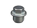 Toyota Oil Drain Plug
 Toyota Oil Pan
 Toyota Piston
 Toyota Cam Gear
 Toyota Crankshaft Gear
 Toyota Crankshaft Seal
 Toyota Crankshaft Thrust Washer
 Toyota Rod Bearing
 Toyota Valve Stem Seal
Browse Toyota Camshaft by Models
Tacoma 4Runner Camry Tundra Corolla RAV4 Highlander Prius Sienna Land Cruiser Pickup FJ Cruiser 86 Sequoia T100 Avalon Celica Supra Yaris Matrix MR2 Solara Venza GR86 Echo Cressida Grand Highlander Paseo Previa Prius C Prius Prime Corolla Cross Crown Crown Signia GR Corolla MR2 Spyder Prius V Starlet Tercel Van Yaris iA Prius Plug-In GR Supra Prius AWD-e RAV4 Prime