×
ToyotaParts- Hello
- Login or Register
- Quick Links
- Live Chat
- Track Order
- Parts Availability
- RMA
- Help Center
- Contact Us
- Shop for
- Toyota Parts
- Scion Parts
My Garage
My Account
Cart
OEM Toyota Cam Gear
Camshaft Gear- Select Vehicle by Model
- Select Vehicle by VIN
Select Vehicle by Model
orMake
Model
Year
Select Vehicle by VIN
For the most accurate results, select vehicle by your VIN (Vehicle Identification Number).
99 Cam Gears found


Toyota Timing Gear Part Number: 13523-0D010
$45.16 MSRP: $62.86You Save: $17.70 (29%)Ships in 1-2 Business DaysProduct Specifications- Other Name: Sprocket, Camshaft Timing; Engine Timing Camshaft Sprocket, Left, Right; Variable Valve Timing Sprocket; Cam Gear; Camshaft Gear; Exhaust Gear; Sprocket; Gear Or Sprocket, Camshaft Timing
- Replaces: 13523-0D020, 13523-22050, 13523-22020


Toyota Timing Gear, Driver Side Part Number: 13050-0D010
$295.08 MSRP: $421.31You Save: $126.23 (30%)Product Specifications- Other Name: Gear Assembly, Camshaft; Engine Timing Camshaft Sprocket, Left; VVT Sprocket; Timing Sprocket; Cam Gear; Camshaft Gear; Intake Gear
- Position: Driver Side
- Replaces: 13050-22011, 13050-22010, 13050-22012


Toyota Camshaft Gear Part Number: 13050-0V011
$325.49 MSRP: $464.73You Save: $139.24 (30%)Product Specifications- Other Name: Gear Assembly, Camshaft; Engine VVT Sprocket; Timing Sprocket; Cam Gear; Intake Gear; Actuator; Gear Assembly, Camshaft Timing
- Replaces: 13050-36011, 13050-0V010, 13050-36010


Toyota Camshaft Gear Part Number: 13070-0V013
$349.26 MSRP: $498.66You Save: $149.40 (30%)Product Specifications- Other Name: Gear Assembly, Camshaft; Engine VVT Sprocket; Timing Sprocket; Cam Gear; Exhaust Gear; Actuator; Sprocket; Gear Assembly, Camshaft Timing Exhaust
- Replaces: 13070-0V010, 13070-0V011, 13070-0V012, 13070-36011, 13070-36010


Toyota Camshaft Gear, Passenger Side Part Number: 13050-28021
$268.17 MSRP: $382.89You Save: $114.72 (30%)Ships in 1 Business DayProduct Specifications- Other Name: Gear Assembly, Camshaft; Engine Timing Camshaft Sprocket; VVT Sprocket; Cam Gear; Gear Assembly, Camshaft Timing
- Position: Passenger Side
- Replaces: 13050-0H010, 13050-28020, 13050-0H030


Toyota Camshaft Gear, Driver Side Part Number: 13080-31030
$327.47 MSRP: $467.55You Save: $140.08 (30%)Ships in 1-3 Business DaysProduct Specifications- Other Name: Gear Assembly, Camshaft; Variable Valve Timing Sprocket; Timing Gear; Cam Gear; Timing Gear Set; Actuator; Gear Assembly, Camshaft Timing Exhaust, Driver Side
- Position: Driver Side
- Replaces: 13080-31020


Toyota Timing Pulley, Driver Side Part Number: 13528-62020
$109.48 MSRP: $153.68You Save: $44.20 (29%)Ships in 1-3 Business DaysProduct Specifications- Other Name: Pulley, Camshaft Timing; Variable Valve Timing Sprocket; Cam Gear; Camshaft Gear
- Manufacturer Note: LH
- Position: Driver Side


Toyota Camshaft Gear Part Number: 13523-AD010
$36.56 MSRP: $50.88You Save: $14.32 (29%)Ships in 1-2 Business DaysProduct Specifications- Other Name: Sprocket, Camshaft Timing; Variable Valve Timing Sprocket; Timing Gear; Cam Gear; Timing Gear Set; Secondary Camshaft Gear; Gear Or Sprocket, Camshaft Timing
- Manufacturer Note: (L)
- Replaces: 13523-31030


Toyota Timing Pulley Part Number: 13523-20020
$48.39 MSRP: $67.35You Save: $18.96 (29%)Ships in 1-3 Business DaysProduct Specifications- Other Name: Pulley, Camshaft Timing; Engine Timing Camshaft Sprocket; Variable Valve Timing Sprocket; Timing Gear; Cam Gear; Camshaft Gear; Timing Gear Set; Gear; Pulley
- Manufacturer Note: (J)
- Replaces: 13523-0A010


Toyota Timing Gear Set Part Number: 13070-31030
$387.93 MSRP: $568.52You Save: $180.59 (32%)Ships in 1-3 Business DaysProduct Specifications- Other Name: Gear Assembly, Camshaft; Variable Valve Timing Sprocket; Timing Gear; Cam Gear; Actuator; Gear Assembly, Camshaft Timing Exhaust


Toyota Pulley Sub-Assembly, Camshaft Timing, Driver Side Part Number: 13056-50050
$121.95 MSRP: $172.64You Save: $50.69 (30%)Ships in 1-3 Business DaysProduct Specifications- Other Name: Pulley Sub-Assembly, Camshaft Timing; Variable Valve Timing Sprocket; Timing Gear; Cam Gear
- Manufacturer Note: (J)
- Position: Driver Side
- Replaces: 13056-0F010


Toyota Timing Pulley, Passenger Side Part Number: 13051-62030
$170.83 MSRP: $241.84You Save: $71.01 (30%)Ships in 1-3 Business DaysProduct Specifications- Other Name: Pulley Sub-Assembly, Camshaft Timing; Variable Valve Timing Sprocket; Cam Gear; Timing Gear; Camshaft Gear; Pulley, Camshaft Timing
- Manufacturer Note: RH
- Position: Passenger Side


Toyota Camshaft Gear, Passenger Side Part Number: 13050-28012
$280.64 MSRP: $400.69You Save: $120.05 (30%)Ships in 1-3 Business DaysProduct Specifications- Other Name: Gear Assembly, Camshaft; Engine Timing Camshaft Sprocket, Right; Variable Valve Timing Sprocket; Cam Gear
- Position: Passenger Side
- Replaces: 13050-28011, 13050-28010


Toyota Timing Gear Set Part Number: 13050-31010
$293.92 MSRP: $419.65You Save: $125.73 (30%)Ships in 1-3 Business DaysProduct Specifications- Other Name: Gear Assembly, Camshaft; Variable Valve Timing Sprocket; Timing Gear; Cam Gear; Gear Assembly, Camshaft Timing


Toyota Timing Pulley, Passenger Side Part Number: 13523-50060
$73.34 MSRP: $102.95You Save: $29.61 (29%)Ships in 1-3 Business DaysProduct Specifications- Other Name: Pulley, Camshaft Timing; Engine Timing Camshaft Sprocket, Right; Variable Valve Timing Sprocket; Timing Gear; Cam Gear; Camshaft Gear; Timing Gear Set; Pulley
- Manufacturer Note: (J)
- Position: Passenger Side


Toyota Timing Pulley, Passenger Side Part Number: 13523-50040
$83.29 MSRP: $116.92You Save: $33.63 (29%)Ships in 1-3 Business DaysProduct Specifications- Other Name: Pulley, Camshaft Timing; Engine Timing Camshaft Sprocket, Right; Variable Valve Timing Sprocket; Timing Gear; Cam Gear; Timing Gear Set; Pulley
- Position: Passenger Side


Toyota Actuator Part Number: 13050-37012
$288.68 MSRP: $412.16You Save: $123.48 (30%)Product Specifications- Other Name: Engine Variable Valve Timing (VVT) Sprocket; Variable Valve Timing Sprocket; Engine VVT Sprocket; Gear Assembly, Camshaft Timing
- Replaced by: 13050-37040


Toyota Gear Assembly, Camshaft Timing Exhaust Part Number: 13070-37010
$311.16 MSRP: $444.27You Save: $133.11 (30%)Ships in 1-3 Business DaysProduct Specifications- Other Name: Gear Assembly, Camshaft
- Manufacturer Note: (J)


Toyota Camshaft Gear Part Number: 13050-0V040
$268.17 MSRP: $382.89You Save: $114.72 (30%)Product Specifications- Other Name: Gear Assembly, Camshaft; Variable Valve Timing Sprocket; Cam Gear; Intake Gear; Actuator; Gear Assembly, Camshaft Timing
- Replaces: 13050-0V030, 13050-0V070, 13050-36030


Toyota Intake Gear Part Number: 13050-0T050
$268.17 MSRP: $382.89You Save: $114.72 (30%)Product Specifications- Other Name: Gear Assembly, Camshaft; Engine VVT Sprocket; Camshaft Adjuster; Cam Gear; Actuator; Gear Assembly, Camshaft Timing
- Manufacturer Note: (L)
- Replaces: 13050-0T021, 13050-0T011, 13050-0T010
| Page 1 of 5 |Next >
1-20 of 99 Results
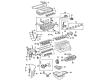
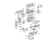
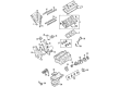
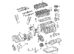
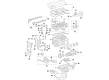
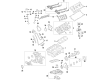
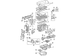
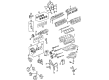
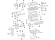
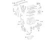
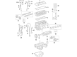
Toyota Cam Gear
OEM parts deliver unmatched quality you can rely on. They pass extensive quality control inspections. Toyota produces them to the official factory specifications. This process helps prevent defects and imperfections. So you can get exceptional lifespan and a flawless fit. Need new OEM Toyota Cam Gear? You'll love our wide selection of genuine options. Shop in minutes and skip the hunt. Our prices are unbeatable, you'll save time and money. It's easy to shop and find the right piece. Our committed customer service team gives professional help from start to finish. Every part includes a manufacturer's warranty. We ship quickly, your parts will arrive fast at your door.
Toyota Cam Gear maintains sharp valve timing which allows engines to breathe right and punch hard at idle. In the years since 1937, Toyota has gained the trust of the world as it has been able to cut down on waste and give crews the power to detect flaws immediately. Toyota is also pursuing hybrid technology, launching the more fuel-efficient Hybrid Synergy Drive and providing ordinary consumers with reduced fuel costs. Toyota also constructed the TNGA and decreased weight, increased rigidity, and cornering became tighter without hurting ride comfort. Toyota continues to add battery-assisted vehicles, small hatchback models to large SUVs, to allow buyers to abandon thrift but not power. Durability remains the brand anchor and there are unlimited numbers of odometers that pass 200,000 miles and cabins, wiring looms, paint, and hinges of the seat continue to work like new thus second and third owners have as much confidence as the original. Cam Gear varies the camshaft position in minute crank-angle steps to match the valve opening with the piston stroke to get as much torque as possible through the rev range and to optimize emissions and fuel consumption. It is not common to replace before excessive wear manifests itself due to the hardened teeth and oil-cooled hub which throws off the heat cycles. Even current engines have Cam Gear that allows variable advance making highway cruising feel relaxed but throttle hits instantly when required. Cam Gear can be applied on several generations of engines and is thus one that can be easily upgraded by its users who will want to experience a smoother idle and longer life.
Toyota Cam Gear Parts and Q&A
- Q: How to install the valve timing controller assembly and Cam Gear on Toyota Celica?A:Oiling the intake camshaft tip and extending it 16mm allows for correct installation of the valve timing controller assembly by setting its timing mark to match the knock pin before mounting onto the camshaft without excessive force. Set the knock pin hole on the camshaft timing sprocket to align with the camshaft knock pin before you use the sprocket to exhaust the camshaft and then install a temporary timing sprocket bolt. Use a wrench to hold the hexagon wrench head of the camshaft before tightening the timing sprocket bolt to 54 Nm (551 kgf-cm, 40 ft-lbf). To position the No.1 cylinder at TDC/compression stage the hexagonal wrench head portion of camshafts needs adjustment for point mark alignment on camshaft timing sprockets which enables continuous rotation of the crankshaft using a crankshaft pulley bolt until the key on the crankshaft faces upwards. Wind the chain vibration damper into place using two bolts which should reach a torque of 9.0 Nm (92 kgf-cm, 80 in.-lbf) for 1ZZ-FE and 20.5 Nm (209 kgf-cm, 15 ft-lbf) for 2ZZ-GE. The timing chain installation for the crankshaft sprocket requires alignment of the yellow link to the timing mark while using Special Service Tool: 09223-22010 only when needed. For 1ZZ-FE engines align the yellow links on camshaft timing sprockets while 2ZZ-GE engines need to align the orange links. Install the chain tensioner slipper with bolt to achieve a torque value of 18.5 Nm (189 kgf-cm, 14 ft-lbf) for 1ZZ-FE or 20.5 Nm (209 kgf-cm, 15 ft-lbf) for 2ZZ-GE. While doing this check that the slipper moves to engage on the cylinder head stopper while avoiding crankshaft rotation. Installation of the crank angle sensor plate requires "F" facing forward while for 1ZZ-FE you must replace packing material from the timing chain cover and water pump contact areas before cleaning thoroughly with 1.5 mm nozzle seal packing (Part No. 08826-00100 or equivalent). Assembly must complete within 3 minutes. Secure the timing chain cover alongside the O-ring by using 16 bolts and 2 nuts which need uniform tightening to appropriate torque values while applying Part No. 08826-00080 or equivalent seal packing at 2 locations. The 2ZZ-GE installation process for timing chain cover and water pump requires the same method as before with proper seal packing techniques and balanced bolt tightening process. Fitting up 2ZZ-GE requires the exhaust manifold alongside the exhaust manifold stay and front exhaust pipe while 1ZZ-FE uses the RH engine mounting bracket which needs seal packing (Part No. 08826-00080 or equivalent) before torque reaches 47 Nm (479 kgf-cm, 35 ft-lbf). For 2ZZ-GE mount the normal right engine bracket by using 4 bolts that require 49 Nm (500 kgf-cm, 36 ft-lbf) torque. The drive belt tensioner should receive inspection for leakage and cracking before its bolts and nut receive their specified torque values. Use Special Service Tool 09960-10010 (or its equivalent tools 09962-01000, 09963-01000) for installing the crankshaft pulley bolt and achieve the specified torque measurements. Install the chain tensioner while achieving correct tension before performing valve timing checks by positioning the crankshaft pulley at mark "0" with synchronized camshaft timing sprocket marks. To install the cylinder head cover of 1ZZ-FE, use seal packing (Part No. 08826-00080 or equivalent) and secure it properly while torquing all bolts and nuts before connecting PCV hoses and the ignition coil. The installation process for the 2ZZ-GE cylinder head cover should proceed similarly with careful attention given to proper torques and connections. The RH engine mounting insulator requires installation in both engine types with torque set to 52 Nm (530 kgf-cm, 38 ft-lbf). The installation process includes attaching the PS pump to the generator and drive belt and air switching valve for 2ZZ-GE and RH engine under cover before the RH front wheel goes on. In conclusion, add the motor coolant before installing front fender apron seals and upper radiator support seals while testing for any coolant leakage when starting the engine.
- Q: How to service and repair the Cam Gear/sprocket on Toyota Solara?A:Starting the camshaft gear/sprocket repair requires removal of the front wheel RH as well as front fender apron seal RH and engine cover sub-assembly No.1 and engine moving control rod with bracket by taking out the 3 bolts. The following service order begins with removing engine mounting stay No.2 RH and engine mounting bracket No.2 RH before proceeding to take off the fan and generator V belt. To service and repair the crankshaft pulley first expand the pulley bolt with Special Service Tool: 09960-10010 and then remove the bolt and pulley completely using Special Service Tool: 09950-40011. Use tools 09308-10010 or 09950-60010 (09951-00200) to extract the timing gear case or timing chain case r oil seal. Before installing an oil seal place MP grease on its lips after inspecting for foreign contaminants and strike it in with Special Service Tool: 09223-22010 and a hammer until it reaches the rear oil seal retainer edge. Remove excess grease from the crankshaft. Install the crankshaft pulley through the pulley set key of its key groove while utilizing Special Service Tool: 09960-10010 (09962-01000, 09963-01000) to tighten the pulley bolt to 170 Nm (1,733 kgf-cm, 125 ft. lbs.). After installing the fan and generator V belt the technician should torque the engine mounting bracket No.2 RH to 52 Nm (531 kgf-cm, 38 ft. lbs.) and the engine mounting stay No.2 RH to 64 Nm (653 kgf-cm, 47 ft. lbs.). The front wheel RH reinstallation procedure begins after bracket and 3 bolting the engine moving control rod with bracket which needs to be torqued to 64 Nm (653 kgf-cm, 47 ft. lbs.). Afterward, check for engine oil leaks.


Related Toyota Parts
 Toyota Valve Cover Gasket
 Toyota Camshaft
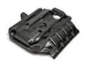 Toyota Engine Cover
 Toyota Crankshaft Pulley
 Toyota Engine Mount
 Toyota Harmonic Balancer
 Toyota Oil Pan
 Toyota Oil Pump
 Toyota Crankshaft Gear
 Toyota Dipstick Tube
 Toyota Oil Pump Gasket
 Toyota Valve Stem Seal
Browse Toyota Cam Gear by Models
Tacoma 4Runner Camry Tundra Corolla RAV4 Highlander Prius Sienna Land Cruiser Pickup FJ Cruiser Sequoia T100 Avalon Celica Supra Yaris Matrix MR2 Solara Venza GR86 Echo C-HR Cressida Grand Highlander Paseo Previa Prius C Prius Prime Corolla Cross Corolla iM Crown Crown Signia GR Corolla MR2 Spyder Prius V Starlet Tercel Van Yaris iA Prius Plug-In GR Supra Prius AWD-e RAV4 Prime