×
ToyotaParts- Hello
- Login or Register
- Quick Links
- Live Chat
- Track Order
- Parts Availability
- RMA
- Help Center
- Contact Us
- Shop for
- Toyota Parts
- Scion Parts
My Garage
My Account
Cart
OEM Toyota Piston
Engine Pistons- Select Vehicle by Model
- Select Vehicle by VIN
Select Vehicle by Model
orMake
Model
Year
Select Vehicle by VIN
For the most accurate results, select vehicle by your VIN (Vehicle Identification Number).
246 Pistons found


Toyota Piston Part Number: 13101-62060-03
$123.72 MSRP: $175.14You Save: $51.42 (30%)Ships in 1-3 Business DaysProduct Specifications- Other Name: Piston Sub-Assembly, With Pin; Piston Sub-Assembly, W/Pin


Toyota Piston Part Number: 13101-75041
$140.28 MSRP: $198.59You Save: $58.31 (30%)Ships in 1-3 Business DaysProduct Specifications- Other Name: Piston Sub-Assembly, With Pin; Piston Sub-Assembly, W/Pin
- Manufacturer Note: STD


Toyota Piston Part Number: 13101-73030
$76.80 MSRP: $107.81You Save: $31.01 (29%)Ships in 1-3 Business DaysProduct Specifications- Other Name: Piston Sub-Assembly, With Pin; Piston Sub-Assembly, W/Pin
- Manufacturer Note: STD,STD

Toyota Piston Part Number: 13101-37240
$78.20 MSRP: $109.77You Save: $31.57 (29%)Ships in 1-3 Business DaysProduct Specifications- Other Name: Piston Sub-Assembly, With Pin; Piston Sub-Assembly, W/Pin
- Manufacturer Note: STD


Toyota Piston Part Number: 13101-0S030
$84.83 MSRP: $119.08You Save: $34.25 (29%)Ships in 1-3 Business DaysProduct Specifications- Other Name: Piston Sub-Assembly, With Pin; Piston Sub-Assembly, W/Pin
- Manufacturer Note: STD


Toyota Piston Sub-Assembly, W/Pin Part Number: 13101-37120
$86.73 MSRP: $121.74You Save: $35.01 (29%)Ships in 1-3 Business DaysProduct Specifications- Other Name: Piston Sub-Assembly, With Pin; Piston
- Manufacturer Note: STD

Toyota Piston Sub-Assembly, W/Pin Part Number: 13101-31092-A0
$92.18 MSRP: $129.39You Save: $37.21 (29%)Ships in 1-3 Business DaysProduct Specifications- Other Name: Piston Sub-Assembly, With Pin; Piston


Toyota Piston Part Number: 13101-31120-B0
$95.50 MSRP: $134.05You Save: $38.55 (29%)Ships in 1-3 Business DaysProduct Specifications- Other Name: Piston Sub-Assembly, With Pin; Piston Sub-Assembly, W/Pin
- Manufacturer Note: STD,MARK B,REFER REPAIR MANUAL


Toyota Piston Part Number: 13211-36041-A0
$98.58 MSRP: $138.37You Save: $39.79 (29%)Ships in 1-3 Business DaysProduct Specifications- Manufacturer Note: MARK A,*107:REFER R/M
- Replaces: 13211-36040-A0


Toyota Piston Part Number: 13101-31030-A0
$96.92 MSRP: $136.05You Save: $39.13 (29%)Ships in 1-2 Business DaysProduct Specifications- Other Name: Piston Sub-Assembly, With Pin; Piston Sub-Assembly, W/Pin
- Manufacturer Note: STD,MARK A,REFER REPAIR MANUAL

Toyota Piston Part Number: 13101-0P020
$99.94 MSRP: $140.28You Save: $40.34 (29%)Ships in 1-3 Business DaysProduct Specifications- Other Name: Engine Piston Set; Cast Piston Set; Piston Sub-Assembly, W/Pin


Toyota Piston Part Number: 13211-28031-B0
$101.66 MSRP: $142.70You Save: $41.04 (29%)Product Specifications- Replaces: 13211-28030-B0


Toyota Piston Part Number: 13101-0S011
$102.02 MSRP: $143.20You Save: $41.18 (29%)Ships in 1-3 Business DaysProduct Specifications- Other Name: Piston Sub-Assembly, With Pin; Engine Piston Set; Cast Piston Set; Piston Sub-Assembly, W/Pin
- Replaces: 13101-0S010


Toyota Piston Part Number: 13101-22032
$105.45 MSRP: $148.02You Save: $42.57 (29%)Ships in 1-3 Business DaysProduct Specifications- Other Name: Piston Sub-Assembly, With Pin; Piston Sub-Assembly, W/Pin
- Manufacturer Note: STD
- Replaces: 13101-22031, 13101-22030


Toyota Piston Sub-Assembly, With Pin Part Number: 13101-50082-02
$111.38 MSRP: $156.34You Save: $44.96 (29%)Ships in 1-3 Business DaysProduct Specifications- Other Name: PISTON SUB-ASSY, W/P; Piston
- Replaces: 13101-0F040-02, 13101-50080-02, 13101-50081-02


Toyota Piston Part Number: 13101-50061-01
$114.36 MSRP: $160.52You Save: $46.16 (29%)Ships in 1-3 Business DaysProduct Specifications- Other Name: Piston Sub-Assembly, With Pin; Piston Sub-Assembly, W/Pin
- Replaces: 13101-0F020-01, 13101-50051-01


Toyota Piston Sub-Assembly, W/Pin, Driver Side Part Number: 13301-50040-02
$114.68 MSRP: $160.98You Save: $46.30 (29%)Ships in 1-3 Business DaysProduct Specifications- Other Name: Piston Sub-Assembly, With Pin; Piston
- Position: Driver Side


Toyota Piston Sub-Assembly, W/Pin Part Number: 13101-66040-01
$143.93 MSRP: $203.75You Save: $59.82 (30%)Product Specifications- Other Name: Piston Sub-Assembly, With Pin; Piston
- Manufacturer Note: STD,MARK 1,REFER REPAIR MANUAL


Toyota Piston Part Number: 13101-46091
$120.66 MSRP: $170.81You Save: $50.15 (30%)Product Specifications- Other Name: Piston Sub-Assembly, With Pin
- Replaces: 13101-46040, 13101-46090


Toyota Piston Sub-Assembly, W/Pin Part Number: 13101-66040-02
$146.16 MSRP: $206.90You Save: $60.74 (30%)Product Specifications- Other Name: Piston Sub-Assembly, With Pin; Piston
- Manufacturer Note: STD,MARK 2,REFER REPAIR MANUAL
| Page 1 of 13 |Next >
1-20 of 246 Results
Toyota Piston
OEM parts deliver unmatched quality you can rely on. They pass extensive quality control inspections. Toyota produces them to the official factory specifications. This process helps prevent defects and imperfections. So you can get exceptional lifespan and a flawless fit. Need new OEM Toyota Piston? You'll love our wide selection of genuine options. Shop in minutes and skip the hunt. Our prices are unbeatable, you'll save time and money. It's easy to shop and find the right piece. Our committed customer service team gives professional help from start to finish. Every part includes a manufacturer's warranty. We ship quickly, your parts will arrive fast at your door.
Toyota Piston transforms the exploding fuel pressure into the crankshaft rotation that catapults each car forward. Toyota maintains the satisfaction of buyers with waste-reducing production that identifies problems early, corrects them during production, and extends a strong quality control strategy to every single daily production shift. The TNGA platform that Toyota uses to reduce costs but improve ride quality features a lower center of gravity, stiffer critical chassis points, and sharper steering to make confident turns. Toyota takes hybrids to all types of cars, including city runabouts and giant SUVs, and allows drivers to achieve mileage through every gallon and limit emissions unobtrusively. Toyota gained credibility throughout the world due to its cars remaining tough, achieving more mileage, not rusting, and remaining in motion even when other competitor vehicles have worn out. The Piston in the cylinder, which is in the process of sealing the expanding gases with close rings, pushes the straight-line push into rotary motion by means of the connecting rod, and it is necessary to be light enough to rev high but stout enough to shoulder thousands of explosions per minute under scorching heat. Piston is frequently made of forged aluminum alloy, with internal cooling channels that drain the heat into oil to keep knock at bay. Piston shapes differ with the trunk styles opposing side forces and the slipper cuts trimming weight to enable rapid RPM ascending. Friction is also reduced by careful skirt geometry that allows engines to turn slick to redline.
Toyota Piston Parts and Q&A
- Q: What are the steps involved in inspecting and preparing piston/connecting rod assemblies before reassembly on Toyota Land Cruiser?A:The committee has noted that before the inspection process can be done, the piston/connecting rod assemblies must be cleaned and the original piston rings extracted from the pistons; new piston rings must also be used when assembling the parts. By employing a piston ring installation tool, it is recommended that the rings be removed carefully, lest the pistons be damaged by nicks and gouges. Carbon deposits must be removed from the top of the piston the hard way: with a hand-held wire brush or fine emery cloth, due to the fact that a wire brush mounted in a motor erodes the soft material of the piston. Carbon accumulated in the ring grooves should be scraped out with a piston ring groove cleaner or with a fragment of the previous ring, being very careful not to scratch the grooves. Following withdrawal of deposits, piston/rod assemblies have to be cleaned with solvent and dried using compressed air while making sure that the oil return holes are unclogged. Generally, pistons and cylinder walls do not require replacement as a rule unless they are badly scored or worn when one decides to rebore the engine block it is not necessary to change the pistons but new piston rings should be fitted to engines that are going for rebuilding. Every piston should be evaluated for the possible cracks, scoring, scuffing, holes, and burned areas on the cylinder and if these are apparent it should also check the cooling and lubrication systems. If pitting corrosion occurs in the form of small pits it may indicate leakage of coolant and this has to be corrected not allow it to reoccur. These values should be checked by a feeler gauge on different places on each ring groove to be sure of which ring is to be installed on each groove; if the clearance is too large, new piston sets may be needed. Here, bore and piston diameter is measured and the difference gives the clearance; this could mean that rebore new pistons and rings would be needed if it is beyond the set standards. The Piston-to-rod clearance should be done by turning the piston and the rod in reciprocating directions, if there is a lot of end play this needs to be corrected, sometimes the automotive machine shop has to resize and replace new pins to the piston. If pistons are to be taken out of the connecting rods, they also should be SENT to the machine shop for checking bend and twist. Main bearings should be inspected by feeling for vibration, and listening for knocks while held in a beam and turning-if they are noisy, new bearings should be installed; caps should be tightened only with fingers and bearing surfaces should be cleaned, which, if old, should be replaced along with caps, if new, connecting rods should be used if rebuilding due to connecting rod knock.
- Q: What steps should be taken to prepare piston/connecting rod assemblies for inspection on Toyota Sienna?A:However, before the inspection process may be done, most of the piston/connecting rod assemblies must be washed and most of the original piston rings must also be removed from the pistons with new one used in the reconditioning. Hold the piston rings between your thumb and forefinger and with the help of piston ring installation tool gently take the rings off from the pistons without scratching the latter. Clean all of the carbon off the top of the piston using a small hand-held wire brush or fine emery paper; DO NOT use a wire brush with a motor attached to it as this is likely to wear a groove in the softer surface of the piston. Carbonaceous deposits from the groove or rust and scale from out sides should be scrape out using a piston ring groove-cleaning tool or a piece of metal broken off the old ring that fits the groove should be used and while doing this should not remove any metal or mars the groove. Once the deposits have been empties, wash the piston/rod assemblies with solvent and blow them off with compressed air, making sure that the oil return holes and the hole in the lower end of each rod are open. Only when the pistons and cylinder walls are worn or damaged and when the engine block is not rebored new pistons are not mandatory, however new piston rings have to be always fitted in any rebuild. Every piston should ought to be checked for cracks, scoring, scuffing, holes and burned out areas since these are the symptoms of overheating, abnormal combustion or spark knock therefore, checking the cooling and lubrication system. Pitting type of corrosion is evidence of coolant penetration into the combustion chamber or crankcase, and this has to be rectified to avoid future occurrences. Check with a new piston ring and a feeler gauge at certain points of a piston ring groove for the correct ring and use the values to compare with the standard then check for the misfit and if it is too wide the piston needs to be replaced. Ensure that the piston to bore clearance is correct by comparing the bore and piston diameter, if not do the following, rebore the block and put new piston and rings in it. Raise the piston and try to turn the piston and rod in opposite directions; if the two parts of a kit exhibits considerable play, it will have to be "repaired." If pistons have to be pulled out from the connecting rods, should be taken to the automotive machine shop for bend and twist. Finally, check for crack and damages with the connecting rods by removing the rod caps and cleaning the bearing areas, for nicks, gouges and crack then replace old bearings and tighten the rod cap by fingers only and new connecting rods should be fitted if the engine is being rebuked for connecting rod knock.


Related Toyota Parts
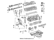
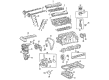
 Toyota Camshaft
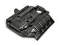 Toyota Engine Cover
 Toyota Crankshaft Pulley
 Toyota Harmonic Balancer
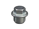 Toyota Oil Drain Plug
 Toyota Oil Pan Gasket
 Toyota Timing Cover
 Toyota Cylinder Head Gasket
 Toyota Camshaft Bearing
 Toyota Exhaust Valve
 Toyota Piston Ring Set
 Toyota Rod Bearing
Browse Toyota Piston by Models
Tacoma 4Runner Camry Tundra Corolla RAV4 Highlander Prius Sienna Land Cruiser Pickup FJ Cruiser 86 Sequoia T100 Avalon Celica Supra Yaris Matrix MR2 Solara Venza GR86 Echo C-HR Cressida Grand Highlander Paseo Previa Prius C Prius Prime Corolla Cross Corolla iM Crown Crown Signia GR Corolla MR2 Spyder Prius V Starlet Tercel Van Yaris iA Prius Plug-In GR Supra Prius AWD-e RAV4 Prime