×
ToyotaParts- Hello
- Login or Register
- Quick Links
- Live Chat
- Track Order
- Parts Availability
- RMA
- Help Center
- Contact Us
- Shop for
- Toyota Parts
- Scion Parts
My Garage
My Account
Cart
OEM Toyota Celica Cam Gear
Camshaft Gear- Select Vehicle by Model
- Select Vehicle by VIN
Select Vehicle by Model
orMake
Model
Year
Select Vehicle by VIN
For the most accurate results, select vehicle by your VIN (Vehicle Identification Number).
13 Cam Gears found


Toyota Celica Timing Gear Part Number: 13523-0D010
$45.16 MSRP: $62.86You Save: $17.70 (29%)Ships in 1-2 Business Days


Toyota Celica Timing Gear, Driver Side Part Number: 13050-0D010
$295.08 MSRP: $421.31You Save: $126.23 (30%)


Toyota Celica Timing Gear Part Number: 13523-35020
$44.80 MSRP: $62.36You Save: $17.56 (29%)Ships in 1-3 Business Days
Toyota Celica Camshaft Gear Part Number: 13523-88301
$176.05 MSRP: $249.22You Save: $73.17 (30%)Ships in 1-3 Business Days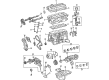
Toyota Celica Timing Gear Part Number: 13523-74040
$59.62 MSRP: $82.98You Save: $23.36 (29%)Ships in 1-3 Business Days
Toyota Celica Timing Gear Part Number: 13529-15010
$82.94 MSRP: $116.42You Save: $33.48 (29%)Ships in 1-3 Business Days


Toyota Celica Timing Gear Part Number: 13523-16070
Toyota Celica Timing Gear Part Number: 13523-63020

Toyota Celica Camshaft Gear Part Number: 13523-43040

Toyota Celica Timing Gear Part Number: 13523-15010
Toyota Celica Exhaust Gear Part Number: 13523-16060
Toyota Celica Timing Gear Part Number: 13523-16050
Toyota Celica Timing Gear Part Number: 13523-74020
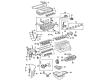
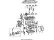
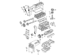
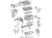
Toyota Celica Cam Gear
Choose genuine Cam Gear that pass strict quality control tests. You can trust the top quality and lasting durability. Shopping for OEM Cam Gear for your Toyota Celica? Our website is your one-stop destination. We stock an extensive selection of genuine Toyota Celica parts. The price is affordable so you can save more. It only takes minutes to browse and find the exact fit. Easily add to cart and check out fast. Our hassle-free return policy will keep you stress-free. We process orders quickly for swift delivery. Your parts will arrive faster, so you can get back on the road sooner.
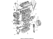
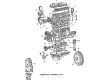
It should be noted that the Toyota Celica Cam Gear is one of the main components that improve vehicles' performance and ensure their higher level of reliability. One of the parts often praised is the ability of the Cam Gear to control the valve timing resulting in better torque and horsepower in different situations. This feature has its significance when applied to the Toyota Celica notably incorporating the premier mode of the engine and thus efficiency, performance and safety. Cam Gear was processed in various styles as the Toyota celica proceeded through its different models; this shows the indeed the manufacturing company Toyota was ever ready to deliver innovative and excellent automobiles. The progress of the Cam Gear technology in Celica Series is indeed strategic in an attempt to achieve the greatest engine power and acceleration response; it becomes this Unique Selling Proposition of this automobile in the market. In addition, compatibility with other Celica series, with turbocharged and AWD options, proves the universality of the Cam Gear once again. Also, later phases, include even better technologies such as phase regulation showing that Toyota's primary goal is to offer a better driving experience to the owners. The Celica Cam Gear not only improves the performance aspect of the Toyota vehicle but also boosts on the safety of the vehicle by maintaining a high level of efficiency for the engine. Because of the outstanding performance and reliability of the Toyota brand, the Toyota Celica Cam Gear is still instrumental in the Toyota Celica's model history for the fans and occasional car owners.
Toyota Celica Cam Gear Parts and Q&A
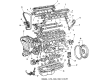
- Q: How to install the valve timing controller assembly and Cam Gear on Toyota Celica?A:Start by application of engine oil to a 16 millimeter zone beginning at the intake camshaft tip then install the valve timing controller assembly after aligning its timing mark to the knock pin and fitting onto the camshaft without applying excessive force. Align the knock pin opening of the camshaft timing sprocket to the knock pin and exhaust the sprocket by placing it on the camshaft before attaching the timing sprocket bolt for now. Use a wrench to hold the hexagon wrench head of the camshaft while tightening the timing sprocket bolt with 45 Nm for 1ZZ-FE and 54 Nm for 2ZZ-GE. The mechanic positions No. 1 cylinder at TDC/compression through hexagonal wrench head camshaft adjustment until both camshaft timing sprocket point marks align. A crankshaft pulley bolt subsequently sets the key at its highest point. Attach both bolts to secure the chain vibration damper and tighten them to 11 Nm (113 kgf-cm, 8 ft. lbs.) for 1ZZ-FE or 20.5 Nm (209 kgf-cm, 15 ft. lbs.) for 2ZZ-GE. When installing the chain in the crankshaft timing sprocket position the yellow link against the timing mark while using Special Service Tool: 09223-22010 if needed, also note that 1ZZ-FE requires the yellow links on camshaft timing sprockets alignment while 2ZZ-GE needs orange links alignment. Before proceeding install the chain-grip slipper with its bolt by tightening it to 18.5 Nm for 1ZZ-FE or 20.5 Nm for 2ZZ-GE. Additionally make sure the slipper can move to catch on the cylinder head stopper without spinning the crankshaft. Position the crank angle sensor plate with its "F" mark pointed toward the front side. 1ZZ-FE owners must replace the old packing material (FIPG) from the timing chain cover before inserting new packing material (Part No. 08826-00100 or equivalent) with a nozzle opening size of 1.5 mm for a 3-minute assembly period. Mount pieces of Sealing Packing (Part No. 08826-00080 or equivalent) at two locations on the unit before installing the timing chain cover along with the O-ring and Water Pump that contains 17 bolts and nut and ensure uniform torquing to specified values. The installation of timing chain covers and water pumps for 2ZZ-GE must follow the same procedure as before but with proper seal packing application and 19 bolt uniform tightening. The RH engine mounting bracket installation requires precise torque values for both engine types before adding the Drive Belt tensioner where leaks should be checked followed by torquing to the specified value. Mount the Crankshaft Position Sensor along with the crankshaft pulley through the use of Special Service Tools 09213-70011 and 09330-00021 with two nuts while tightening them to their specified torque points. The chain tensioner installation includes placement of its O-ring in proper position followed by crankshaft rotation to establish the slipper position. Use the crankshaft pulley groove to check valve timing alignment at timing mark "0" while confirming the camshaft timing sprocket alignment. Installation of cylinder head cover must occur using proper torque values while connecting PCV hoses and adding the Ignition Coil to 1ZZ-FE. The process of installing the cylinder head cover for 2ZZ-GE requires ventilation hose connection and ignition coil assembly while maintaining the same installation sequence. The mounting insulator for the RH engine must be installed with the correct torque values before the PS pump and generator receive their installation alongside new drive belt and under cover and front wheel and engine coolant filling and seal installation before starting the engine for leak testing.

Related Toyota Celica Parts
 Toyota Celica Oil Pan
 Toyota Celica Timing Belt
 Toyota Celica Valve Cover Gasket
 Toyota Celica Oil Pan Gasket
 Toyota Celica Exhaust Valve
 Toyota Celica Oil Pump Gasket
 Toyota Celica Piston
 Toyota Celica Spool Valve
 Toyota Celica Timing Chain Tensioner
 Toyota Celica Timing Cover
 Toyota Celica Valve Stem Seal
 Toyota Celica Variable Timing Sprocket