×
ToyotaParts- Hello
- Login or Register
- Quick Links
- Live Chat
- Track Order
- Parts Availability
- RMA
- Help Center
- Contact Us
- Shop for
- Toyota Parts
- Scion Parts
My Garage
My Account
Cart
OEM 2004 Toyota Celica Cam Gear
Camshaft Gear- Select Vehicle by Model
- Select Vehicle by VIN
Select Vehicle by Model
orMake
Model
Year
Select Vehicle by VIN
For the most accurate results, select vehicle by your VIN (Vehicle Identification Number).
2 Cam Gears found


2004 Toyota Celica Timing Gear
Part Number: 13523-0D010$43.84 MSRP: $61.03You Save: $17.19 (29%)Ships in 1-2 Business DaysProduct Specifications- Other Name: Sprocket, Camshaft Timing; Engine Timing Camshaft Sprocket, Left, Right; Variable Valve Timing Sprocket; Cam Gear; Camshaft Gear; Exhaust Gear; Sprocket; Gear Or Sprocket, Camshaft Timing
- Replaces: 13523-0D020, 13523-22050, 13523-22020
- Part Name Code: 13523
- Item Weight: 0.80 Pounds
- Item Dimensions: 4.5 x 3.9 x 1.6 inches
- Condition: New
- Fitment Type: Direct Replacement
- SKU: 13523-0D010
- Warranty: This genuine part is guaranteed by Toyota's factory warranty.


2004 Toyota Celica Timing Gear, Driver Side
Part Number: 13050-0D010$286.46 MSRP: $409.01You Save: $122.55 (30%)Product Specifications- Other Name: Gear Assembly, Camshaft; Engine Timing Camshaft Sprocket, Left; VVT Sprocket; Timing Sprocket; Cam Gear; Camshaft Gear; Intake Gear
- Position: Driver Side
- Replaces: 13050-22011, 13050-22010, 13050-22012
- Item Weight: 2.40 Pounds
- Item Dimensions: 4.5 x 4.5 x 2.0 inches
- Condition: New
- SKU: 13050-0D010
- Warranty: This genuine part is guaranteed by Toyota's factory warranty.
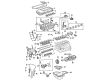
2004 Toyota Celica Cam Gear
Looking for affordable OEM 2004 Toyota Celica Cam Gear? Explore our comprehensive catalogue of genuine 2004 Toyota Celica Cam Gear. All our parts are covered by the manufacturer's warranty. Plus, our straightforward return policy and speedy delivery service ensure an unparalleled shopping experience. We look forward to your visit!
2004 Toyota Celica Cam Gear Parts Q&A
- Q: How to install the valve timing controller assembly and Cam Gear on 2004 Toyota Celica?A: First apply engine oil to the intake camshaft tip and extend it 16mm forward then put the timing mark from the valve timing controller assembly to the knock pin before installing it to the camshaft carefully. The installation of the camshaft timing sprocket requires positioning its knock pin hole with the camshaft knock pin followed by sprocket rotation to face the camshaft before installing the temporary timing sprocket bolt. Secure the hexagonal wrench head of the camshaft by using a wrench to torque the timing sprocket bolt at 54 Nm (551 kgf-cm, 40 ft-lbf). Set No.1 cylinder to TDC/compression by rotating the hexagonal wrench head portion of the camshafts until the point marks of the camshaft timing sprockets align. Next, use a crankshaft pulley bolt to turn the crankshaft and position its key upward. The chain vibration damper needs two bolts torqued to 9.0 Nm (92 kgf-cm, 80 in-lbf) for 1ZZ-FE engines and 20.5 Nm (209 kgf-cm, 15 ft-lbf) for 2ZZ-GE types. To mount the timing chain onto the crankshaft timing sprocket, use Special Service Tool: 09223-22010 and align the yellow link with the timing mark if needed. For 1ZZ-FE models, ensure the yellow links on both the camshaft timing sprockets line up correctly but 2ZZ-GE requires aligning the orange links instead. The procedure requires installation of the chain tensioner slipper using the bolt followed by torquing it to 18.5 Nm for 1ZZ-FE and 20.5 Nm for 2ZZ-GE while making sure the slipper reaches and stays on the cylinder head stopper without turning the crankshaft. Place the crank angle sensor plate in position by positioning its "F" mark towards the front direction. Install the timing chain cover and O-ring on 1ZZ-FE by applying seal packing (Part No 08826-00100 equivalent with a 1.5 mm nozzle before putting on the water pump using 16 bolts and two nuts while torquing to specified torque values. The installation of the timing chain cover and water pump for 2ZZ-GE requires using Part No. 08826-00080 or equivalent seal packing. The installation process begins with fitting the exhaust manifold along with its support and front exhaust pipe on 2ZZ-GE engines. Next, install the right-hand engine mounting bracket while applying the specified packing material (Part No. 08826-00080 or equivalent) to the threads which requires 47 Nm (479 kgf-cm, 35 ft-lbf) torque on 1ZZ-FE and 49 Nm (500 kgf-cm, 36 ft-lbf) torque on 2ZZ-GE units. The drive belt tensioner bolt should receive torque of 69 Nm (704 kgf-cm, 51 ft-lbf) for 1ZZ-FE models while 2ZZ-GE models require 100 Nm (1,020 kgf-cm, 74 ft-lbf) and the nut should reach a torque of 29 Nm (296 kgf-cm, 21 ft-lbf). Use Special Service Tool: 09960-10010 (09962-01000, 09963-01000) for the pulley bolt to install the crankshaft position sensor with crankshaft pulley. Torque to 138 Nm (1,409 kgf-cm, 102 ft-lbf) for 1ZZ-FE and 120 Nm (1,224 kgf-cm, 89 ft-lbf) for 2ZZ-GE. Install the chain tensioner with O-ring properly positioned and tighten its nuts to 9.0 Nm (92 kgf-cm, 80 in-lbf). Flush the crankshaft in two rotations while counting its movement before verifying that the plunger pushes the slipper into position. Determine valve timing by positioning the crankshaft pulley groove at "0" timing while verifying the straight alignment of the camshaft timing sprocket. When installing a cylinder head cover on 1ZZ-FE models, users need to apply Part No. 08826-00080 or equivalent seal packing on the surface then tighten all bolts and nuts to specified torque requirements. When installing 2ZZ-GE components apply the provided instructions while performing the work within a three-minute timeframe. The installation process includes mounting the insulator followed by PS pump and generator then installing the drive belt with the air switching valve before adding the RH engine under cover together with the front wheel and coolant followed by front fender apron seal before starting the engine to confirm coolant leakages.
Related 2004 Toyota Celica Parts
 2004 Toyota Celica Engine Mount
 2004 Toyota Celica Oil Pan
 2004 Toyota Celica Oil Pump
 2004 Toyota Celica Crankshaft Seal
 2004 Toyota Celica Cylinder Head Gasket
 2004 Toyota Celica Oil Filler Cap
 2004 Toyota Celica Piston
 2004 Toyota Celica Piston Ring Set
 2004 Toyota Celica Rod Bearing
 2004 Toyota Celica Timing Chain Tensioner
 2004 Toyota Celica Timing Cover
 2004 Toyota Celica Variable Timing Sprocket