×
ToyotaParts- Hello
- Login or Register
- Quick Links
- Live Chat
- Track Order
- Parts Availability
- RMA
- Help Center
- Contact Us
- Shop for
- Toyota Parts
- Scion Parts
My Garage
My Account
Cart
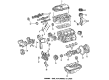
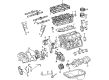
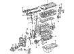
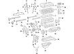
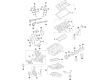
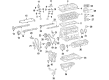
OEM Toyota Tacoma Camshaft
Cam- Select Vehicle by Model
- Select Vehicle by VIN
Select Vehicle by Model
orMake
Model
Year
Select Vehicle by VIN
For the most accurate results, select vehicle by your VIN (Vehicle Identification Number).
21 Camshafts found


Toyota Tacoma Camshaft Part Number: 13501-31040
$547.97 MSRP: $803.06You Save: $255.09 (32%)Ships in 1-3 Business Days

Toyota Tacoma Camshaft Part Number: 13502-62030
$236.25 MSRP: $337.31You Save: $101.06 (30%)Ships in 1-3 Business Days

Toyota Tacoma Camshaft Sub-Assembly Part Number: 13054-62030
$236.25 MSRP: $337.31You Save: $101.06 (30%)Ships in 1-3 Business Days


Toyota Tacoma Camshaft Part Number: 13053-62050
$343.55 MSRP: $490.51You Save: $146.96 (30%)Ships in 1-3 Business Days
Toyota Tacoma Camshaft Part Number: 13054-31010
$556.25 MSRP: $815.19You Save: $258.94 (32%)Ships in 1-3 Business Days
Toyota Tacoma Camshaft Part Number: 13502-31010
$556.25 MSRP: $815.19You Save: $258.94 (32%)Ships in 1-3 Business Days
Toyota Tacoma Camshaft Part Number: 13053-31010
$556.25 MSRP: $815.19You Save: $258.94 (32%)Ships in 1-3 Business Days

Toyota Tacoma Camshaft Part Number: 13502-F0080
$344.69 MSRP: $505.14You Save: $160.45 (32%)Ships in 1-2 Business DaysToyota Tacoma Camshaft Sub-Assembly, Intake Part Number: 13501-F0080
$344.69 MSRP: $505.14You Save: $160.45 (32%)Ships in 1-2 Business Days
Toyota Tacoma Intake Camshaft Part Number: 13501-75902
$354.22 MSRP: $519.12You Save: $164.90 (32%)Ships in 1-3 Business Days
Toyota Tacoma Exhaust Camshaft Part Number: 13502-75080
$411.20 MSRP: $602.62You Save: $191.42 (32%)Ships in 1-3 Business DaysToyota Tacoma Intake Camshaft Part Number: 13501-75903
$440.71 MSRP: $645.86You Save: $205.15 (32%)
Toyota Tacoma Camshaft Sub-Assembly Part Number: 13502-31110
$548.42 MSRP: $803.72You Save: $255.30 (32%)Ships in 1-3 Business Days
Toyota Tacoma Camshaft Sub-Assembly Part Number: 13501-31140
$548.42 MSRP: $803.72You Save: $255.30 (32%)Ships in 1-3 Business Days
Toyota Tacoma Camshaft Sub-Assembly Part Number: 13054-31110
$548.42 MSRP: $803.72You Save: $255.30 (32%)Ships in 1-3 Business Days
Toyota Tacoma Camshaft Sub-Assembly Part Number: 13053-31110
$582.36 MSRP: $853.46You Save: $271.10 (32%)Ships in 1-3 Business Days
Toyota Tacoma Intake Camshaft Part Number: 13501-75071
$323.86 MSRP: $462.40You Save: $138.54 (30%)Ships in 1-3 Business Days
Toyota Tacoma Camshaft Part Number: 13501-62050
$340.60 MSRP: $499.16You Save: $158.56 (32%)
Toyota Tacoma Camshaft Part Number: 13502-75060
$323.86 MSRP: $462.40You Save: $138.54 (30%)
Toyota Tacoma Exhaust Camshaft Part Number: 13502-75901
$354.22 MSRP: $519.12You Save: $164.90 (32%)
| Page 1 of 2 |Next >
1-20 of 21 Results
Toyota Tacoma Camshaft
Choose genuine Camshaft that pass strict quality control tests. You can trust the top quality and lasting durability. Shopping for OEM Camshaft for your Toyota Tacoma? Our website is your one-stop destination. We stock an extensive selection of genuine Toyota Tacoma parts. The price is affordable so you can save more. It only takes minutes to browse and find the exact fit. Easily add to cart and check out fast. Our hassle-free return policy will keep you stress-free. We process orders quickly for swift delivery. Your parts will arrive faster, so you can get back on the road sooner.
Toyota Tacoma Camshaft Parts and Q&A
- Q: How to remove the camshaft on Toyota Tacoma?A:One should begin camshaft removal of the 2TR-FE engine by disconnecting the negative battery cable. The engine under cover of No. 1 must be removed on 4WD models by destroying all 4 securing bolts. Engine coolant loss precedes removal of the radiator support to frame seal LH and subsequently removal of the fan shroud. Before moving onto the next step remove the intake air connector together with the air cleaner cap sub-assembly. The first step involves disconnecting ignition coil connectors alongside throttle with motor body connector VSV connector and camshaft position sensor connector while engine wire harness clamps incur removal too. You must then remove the ignition coils then ventilation hose before extracting 19 bolts and 2 nuts. The timing chain guide requires removal after you remove its 2 bolts and O-ring. Turn the crankshaft pulley clockwise to reach TDC/compression of No. 1 cylinder while both the timing mark notch aligns with "0" and both camshaft timing gear marks are directly facing each other. Apply paint marks on the timing chain plates to match the camshaft timing gear marks. Use an adjustable wrench to grip the hexagonal lobe of the No. 2 camshaft while removing its bolt and extracting the head straight screw plug with a hexagon wrench sized 10 mm. The service hole of the chain tensioner receives a screwdriver which holds the stopper plate lifted while turning the No. 2 camshaft clockwise to push the plunger of the chain tensioner. After removing the screwdriver continue holding the adjustable wrench at its position before inserting and taping a 3.0 mm (0.118 in.) diameter tool into the stopper plate hole. Start by taking off the bolt and camshaft timing gear before you evenly loosen and carefully remove the specified order of 21 bearing cap bolts when the camshaft rests flat. Start by removing the camshaft oil delivery pipe with its O-ring before proceeding to remove the camshaft bearing cap No. 1 and the 8 camshaft bearing caps No. 2 followed by extracting the camshaft itself with the No. 2 camshaft without harming the cylinder head components. Secure the chain by string or wire to block outside items from passing through the engine area. When working with the camshaft timing gear assembly position the camshaft in a vise and do not damage it by applying vinyl tape across the four oil paths of the cam journal then puncture the tape from both sides at 200kPa (2.0 kgf/cm2, 29 psi) air pressure to both paths. Reduce pressure from the retard side path of the camshaft timing gear until it turns toward advance before letting air pressure escape from the retard path and finally from the advance path. Remove only the sole fringe bolt of the camshaft timing gear but constrain your actions against all remaining 3 bolts.
- Q: How to install the camshaft timing gear assembly, camshafts, timing chain, chain tensioner, cylinder head cover, ignition components, and complete final checks including torque specifications and sealing procedures on Toyota Tacoma?A:The installation procedure requires placement of the key groove and straight pin followed by light gear pressure against the camshaft and simultaneous gear turning as well as pushing at the groove insertion point while avoiding retard angle movement of the camshaft timing gear. The gear fringe must have no clearance from the camshaft while you tighten the fringe bolt to 78 Nm with torque and verify the camshaft timing gear movement into the extreme retard position. Put fresh engine oil on the camshaft cam section and cylinder head journals before installing the chain on the timing gear with painted markings directed toward the timing position while adjusting both camshafts correctly. Before final installation who should install the No. 1 camshaft bearing cap while checking that each No. 2 camshaft bearing cap occupies its proper position. Then place a new O-ring on the No. 1 camshaft bearing cap. Install the provisionary camshaft oil delivery pipe before tightening its mounting bolts according to the sequence and torque specifications of 12 Nm and 16 Nm. First check that each timing mark is correctly positioned then install the timing chain onto the camshaft timing gear and align the No. 2 camshaft straight pin with the camshaft timing gear straight pin hole before reducing the No. 2 camshaft rotation by using the hexagonal lobe when necessary. Attach an adjustable wrench to the hexagonal lobe while tightening the bolt to 78 Nm (795 kgf-cm, 58 ft-lbf). Using Toyota Genuine Adhesive 1324, Three Bond 1324 or equivalent apply adhesive to 2 or 3 threads of the head straight screw plug on the timing gear case before installing it with a 10 mm socket hexagon wrench to 17 Nm (170 kgf-cm, 12 ft-lbf) torque. A new O-ring should be installed on the camshaft bearing cap followed by the timing chain guide which must receive two bolts tightened to 10 Nm (102 kgf-cm, 7 ft-lbf). Install Toyota Genuine Seal Packing Black or Three Bond 1207B or an equivalent product at designated sites while ensuring surface oil removal before putting the cylinder head cover in place within three minutes and avoiding oil application for at least two post-installation hours. The cylinder head cover requires provisional bolt-on installation with 19 bolts together with 2 nuts. Begin by tightening bolts A to 9.0 Nm (92 kgf-cm, 80 in-lbf) then apply identical torque on nuts and bolts B before repeating the torque sequence for bolts A. Connect the ventilation hose followed by Ignition Coil bolt-on at 9.0 Nm (92 kgf-cm, 80 in-lbf) and engine wire harness clamp application and finally connect the camshaft position sensor connector, VSV connector, throttle with motor body connector, and ignition coil connectors. For the last step install Installation requires the under cover of the No. 1 engine secured with four bolts up to 30 Nm (306 kgf-cm, 22 ft-lbf) torque then the cable needs a 3.9 Nm (40 kgf-cm, 35 in-lbf) torque connection to the negative battery terminal. Before finishing the work add engine coolant while confirming no coolant or oil leakage occurs.


Related Toyota Tacoma Parts
 Toyota Tacoma Oil Pan
 Toyota Tacoma Cylinder Head
 Toyota Tacoma Dipstick
 Toyota Tacoma Oil Drain Plug Gasket
 Toyota Tacoma Balance Shaft Gear
 Toyota Tacoma Crankshaft Gear
 Toyota Tacoma Cylinder Head Gasket
 Toyota Tacoma Spool Valve
 Toyota Tacoma Timing Chain Guide
 Toyota Tacoma Timing Cover Gasket
 Toyota Tacoma Timing Idler Gear
 Toyota Tacoma Valve Stem Seal