×
ToyotaParts- Hello
- Login or Register
- Quick Links
- Live Chat
- Track Order
- Parts Availability
- RMA
- Help Center
- Contact Us
- Shop for
- Toyota Parts
- Scion Parts
My Garage
My Account
Cart
OEM Toyota Tacoma Timing Belt
Engine Timing Belt- Select Vehicle by Model
- Select Vehicle by VIN
Select Vehicle by Model
orMake
Model
Year
Select Vehicle by VIN
For the most accurate results, select vehicle by your VIN (Vehicle Identification Number).
1 Timing Belt found


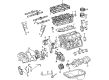
Toyota Tacoma Timing Belt Part Number: 13568-YZZ03
$58.42 MSRP: $81.32You Save: $22.90 (29%)Ships in 1-3 Business Days
Toyota Tacoma Timing Belt
Choose genuine Timing Belt that pass strict quality control tests. You can trust the top quality and lasting durability. Shopping for OEM Timing Belt for your Toyota Tacoma? Our website is your one-stop destination. We stock an extensive selection of genuine Toyota Tacoma parts. The price is affordable so you can save more. It only takes minutes to browse and find the exact fit. Easily add to cart and check out fast. Our hassle-free return policy will keep you stress-free. We process orders quickly for swift delivery. Your parts will arrive faster, so you can get back on the road sooner.
Toyota Tacoma Timing Belt Parts and Q&A
- Q: How to remove the timing belt on Toyota Tacoma?A:Beginning the timing belt replacement requires removal of the under engine cover and draining engine coolant followed by upper radiator hose separation. The PS pump requires disconnect from the engine through the removal of two PS air hoses from both air intake chamber and resonator as well as the frame-mounted PS pressure tube bolt and Drive Belt and bolt-and-nut combination to detach the PS pump. The A/C compressor requires disconnection from the engine using three procedures which include removing the drive belt along with the A/C compressor connector and four bolts. Begin the process by loosening the fan and its fluid coupling system along with the fan pulleys and then remove the generator drive belt. After which remove the No.2 fan shroud as well as the fan controlled by a fluid coupling and its pulleys and finally the A/C compressor bracket through the use of five bolts. You should remove all parts of the oil dipstick system which include the bolt along with the dipstick and guide as well as the O-ring. To begin the Camshaft position sensor connector needs disconnecting while four high-tension cord clamps must be removed and six bolts must be unfastened from the No.2 timing belt cover. Unscrew the multivariable pump adjusting strut and its attached PS pump strut nut before removing the bolt and fan bracket together with the nut. To loosen the crankshaft pulley bolt first apply Special Service Tool: 09213-54015 (90119-08216), 09330-00021 and then disconnect the pulley bolt with Special Service Tool: 09950-50011 (09951-05010, 09952-05010, 09953-05020, 09954-05030), remove the pulley from the crankshaft. A service bolt can be used while Special Service Tool: 09950-50011 (09951-05010, 09952-05010, 09953-05020, 09954-05030) to remove the pulley when needed. Start by removing the starter wire bracket and No.1 timing belt cover through the procedure of disassembling two bolts holding the starter wire bracket while you also take off four bolts securing the timing belt cover. Therefore the first step is to place the crankshaft pulley bolt temporarily to set the No.1 cylinder at TDC/compression before aligning timing marks by turning the crankshaft. Finally inspect the alignment between camshaft timing pulleys and No.3 timing belt cover. Timed marks located on the front and three other areas should be checked; new marks should be added before removing the timing belt when any marks are missing. Begin by unlatching the timing belt tensioner through bolts alternately then take out the two bolts together with tensioner and dust boot before removing the timing belt. A technician should use Special Service Tool: 09960-10010 (09962-01000, 09963-01000) to loosen the camshaft timing pulley bolt before removing the bolt together with the knock pin and timing pulley. You should perform this procedure once more for the LH timing pulley of the camshaft. The No.2 idler pulley removal starts with bolting removal while the No.1 idler pulley demands a 10 mm hexagon wrench during the pivot bolt, idler pulley, and plate washer extraction process. Dismantle the crankshaft timing pulley through the application of Special Service Tool: 09950-50011 (09951-05010, 09952-05010, 09953-05020, 09954-05010 with optional service bolt usage. Check the timing belt for defects that include bending, twisting and touching oil or water or steam but confirm proper installation without damage. Examine the idler pulleys for fluid leaks together with their regular operation while verifying the timing belt tensioner has either no fluid leakages or works properly. First install the crankshaft timing pulley with its key positioned correctly at the key groove then cover it with the pulley after which install the No.1 idler pulley through a 10 mm hexagon wrench until it reaches 35 Nm torque (350 kgf-cm, 26 ft. lbs. torque). Use Special Service Tool: 09960-10010 (09962-01000, 09963-01000) to torque the pulley bolt of the LH camshaft timing pulley at 110 Nm (1,100 kgf-cm, 81 ft. lbs.). The flange side of this pulley needs to face outward with knock pin alignment. After repeating this procedure apply it to the RH camshaft timing pulley. To start the procedure align the No.1 cylinder at TDC compression while you temporarily fasten the crankshaft pulley bolt by its marks. The timing belt installation requires a cool engine and clean pulleys in addition to placing installation marks directly on timing marks. The timing belt tensioner setup requires users to push in the push rod while aligning holes then placing the dust boot. To complete installation of the timing belt tensioner use two bolts which must be torqued to 27 Nm (280 kgf-cm, 20 ft. lbs.). Next check valve timing through crankshaft rotation and timing mark alignment. Industrial placement of the timing belt guide requires installation of the No.1 timing belt cover alongside the starter wire bracket while checking gasket quality. Use Special Service Tool: 09213-54015 (90119-08216) and 09330-00021 to bolt the crankshaft pulley with its set key properly aligned at 295 Nm (3,000 kgf-cm but torque to 217 ft. lbs. Fasten the fan bracket and A/C compressor bracket and surmountarily secure the fan along with its fluid coupling and fan pulleys. The installation process continues with fitting the No.2 fan shroud followed by generator drive belt adjustment and fan tightening with fluid coupling and fan pulley to 5.4 Nm (54 kgf-cm, 48 inch lbs.). Next, connect the A/C compressor to the engine with four bolts at 25 Nm (250 kgf-cm, 18 ft. lbs.) alongside connecting the PS pump to the engine, while all bolts must be securely torqued to specifications. The last steps begin with connecting the upper radiator hose while adding coolant to the engine and then starting the engine to detect leaks before installing the engine under cover followed by a road test for checking abnormal engine noise and operation. Once these checks are complete a final inspection of engine coolant level is performed.

Related Toyota Tacoma Parts
 Toyota Tacoma Oil Filter
 Toyota Tacoma Oil Pan
 Toyota Tacoma Valve Cover Gasket
 Toyota Tacoma Crankshaft Gear
 Toyota Tacoma Dipstick Tube
 Toyota Tacoma Engine Mount
 Toyota Tacoma Oil Pump
 Toyota Tacoma Oil Pump Gasket
 Toyota Tacoma Piston Ring Set
 Toyota Tacoma Rod Bearing
 Toyota Tacoma Timing Chain Tensioner
 Toyota Tacoma Timing Cover