×
ToyotaParts- Hello
- Login or Register
- Quick Links
- Live Chat
- Track Order
- Parts Availability
- RMA
- Help Center
- Contact Us
- Shop for
- Toyota Parts
- Scion Parts
My Garage
My Account
Cart
OEM Toyota Tacoma Timing Chain
Engine Timing Chain- Select Vehicle by Model
- Select Vehicle by VIN
Select Vehicle by Model
orMake
Model
Year
Select Vehicle by VIN
For the most accurate results, select vehicle by your VIN (Vehicle Identification Number).
10 Timing Chains found


Toyota Tacoma Timing Chain Part Number: 13507-0P010
$73.58 MSRP: $103.28You Save: $29.70 (29%)Ships in 1-2 Business Days

Toyota Tacoma Timing Chain Part Number: 13506-AD010
$264.79 MSRP: $378.07You Save: $113.28 (30%)Ships in 1-3 Business Days

Toyota Tacoma Secondary Chain Part Number: 13507-AD010
$98.46 MSRP: $138.21You Save: $39.75 (29%)Ships in 1-2 Business Days


Toyota Tacoma Timing Chain Part Number: 13506-75020
$246.50 MSRP: $351.95You Save: $105.45 (30%)Ships in 1-3 Business Days

Toyota Tacoma Secondary Chain Part Number: 13507-75030
$145.92 MSRP: $206.57You Save: $60.65 (30%)Ships in 1-3 Business Days


Toyota Tacoma Timing Chain Part Number: 13507-75010
$175.09 MSRP: $249.98You Save: $74.89 (30%)Ships in 1-3 Business Days
Toyota Tacoma Timing Chain Part Number: 13506-75010
$214.46 MSRP: $306.20You Save: $91.74 (30%)Ships in 1-3 Business Days
Toyota Tacoma Chain Sub-Assembly Part Number: 13506-0P030
$241.38 MSRP: $344.63You Save: $103.25 (30%)Ships in 1-2 Business Days
Toyota Tacoma Timing Chain Part Number: 13506-75070
$247.20 MSRP: $352.95You Save: $105.75 (30%)Ships in 1-3 Business Days

Toyota Tacoma Chain Sub-Assembly Part Number: 13506-F0030
$207.82 MSRP: $296.73You Save: $88.91 (30%)Ships in 1-2 Business Days
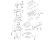
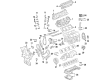
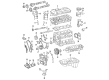
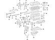
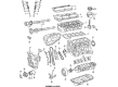
Toyota Tacoma Timing Chain
Choose genuine Timing Chain that pass strict quality control tests. You can trust the top quality and lasting durability. Shopping for OEM Timing Chain for your Toyota Tacoma? Our website is your one-stop destination. We stock an extensive selection of genuine Toyota Tacoma parts. The price is affordable so you can save more. It only takes minutes to browse and find the exact fit. Easily add to cart and check out fast. Our hassle-free return policy will keep you stress-free. We process orders quickly for swift delivery. Your parts will arrive faster, so you can get back on the road sooner.
Toyota Tacoma Timing Chain Parts and Q&A
- Q: How to install the No. 2 Timing Chain sub-assembly and complete the assembly process on Toyota Tacoma?A:During installation of the No. 2 chain sub-assembly position the chain marks to match the timing marks on the crankshaft and balanceshaft timing sprockets while placing the crankshaft timing sprocket mark at the large timing mark of the balanceshaft drive gear. Connect and fasten the balanceshaft drive gear shaft through the gear thrust plate hole while the small timing mark aligns with the balanceshaft timing gear markings. Tighten the bolt at the drive gear to 25 Nm (250 kgf-cm, 18 ft-lbf). Check that each timing mark shows proper alignment. Assemble the No. 2 chain tensioner assembly with its nut to 18 Nm (185 kgf-cm, 13 ft-lbf) while maintaining the 3.0 mm (0.118 in.) diameter bar inside to prevent chain tensioner positioning which should be removed after eliminating any contact between the vibration damper and chain. First tighten and install bolt 1 on chain vibration damper No 3 at 18 Nm then move to bolt installation of chain vibration damper No 2 to 27 Nm before removing the pin from the chain tensioner assembly. You should then install the crankshaft timing gear or sprocket according to manufacturing illustration followed by a proper bolted installation of the No. 1 chain vibration damper with torque set at 21 Nm (214 kgf-cm, 15 ft-lbf). The sprocket and gear assembly needs to be mounted while timing marks align their painted indicators. A rope should secure the crankshaft timing sprocket chain to stop gear jumping yet the rope must be removed when the chain tensioner gets installed. Place the chain tensioner slipper onto its mating position and fasten it with a bolt tightened to 21 Nm (214 kgf-cm, 15 ft-lbf) before installing the No. 1 chain tensioner assembly using new gasket material with a bolt and nut that requires 10 Nm (102 kgf-cm, 7 ft-lbf) torque. The install process starts with new O-rings placed on the timing chain guide before torquing the 2 bolts to 10 Nm (102 kgf-cm, 7 ft-lbf). Proceed to install the timing chain cover. Use Toyota Genuine Seal Packing Black together with Three Bond 1207B or equivalent to apply continuous beads having a specified width of 2 to 3 mm (0.079 to 0.118 in.) for the oil pan sub-assembly. Clean the contact surface of oil before installing the crankcase after no more than 3 minutes of applying the seal packing while engine start should be delayed for at least 2 hours after installation. First attach the oil pan with 18 bolts and 2 nuts while it stays loose before tightening all fasteners to 26 Nm (265 kgf-cm, 19 ft-lbf) in the designated sequence. Use two bolts and two nuts to install the oil strainer sub-assembly with its new gasket by tightening them to 26 Nm (265 kgf-cm, 19 ft-lbf). Then install the No. 2 oil pan sub-assembly after applying seal packing two to three millimeters wide (0.118 to 0.157 in.). Finally, provisionally fasten it using 18 bolts and two nuts which should be uniformly tightened to 9.0 Nm (92 kgf-cm, 80 in-lbf). Install a new gasket and the drain plug, then proceed with the installation of the oil level gage sub-assembly, crankshaft pulley, cylinder head cover sub-assembly, No. 1 intake manifold to head gasket, Camshaft Position Sensor, Crankshaft Position Sensor, idle pulley assembly with bracket, No. 1 idler pulley sub-assembly tightened to 43 Nm (438 kgf-cm, 32 ft-lbf), V-ribbed belt tensioner assembly, generator assembly, intake air connector, rear end plate with 2 bolts tightened to 18 Nm (184 kgf-cm, 13 ft-lbf), drive plate and ring gear sub-assembly for automatic transmission, flywheel sub-assembly for manual transmission, Clutch Disc assembly, clutch cover assembly, engine assembly, automatic transmission assembly, manual transmission unit assembly, Exhaust Pipe assembly front, exhaust pipe assembly tail, engine wire connection, No. 1 air injection hose connection, fuel vapor feed hose assembly connection, No. 2 fuel hose connection, fuel hose connection, water hose sub-assembly installation, radiator hose inlet installation, compressor and magnetic clutch installation with 4 bolts tightened to 21 Nm (214 kgf-cm, 16 ft-lbf) and connector attached, No. 2 radiator hose installation, vane pump assembly installation with 2 bolts tightened to 21 Nm (214 kgf-cm, 16 ft-lbf) and connector attached, air cleaner case installation with 3 bolts tightened to 12 Nm (122 kgf-cm, 9 ft-lbf), air cleaner filter element sub-assembly installation, air cleaner cap sub-assembly installation, fan shroud installation, radiator support to frame seal LH installation, battery tray installation, battery installation, adding engine oil, adding engine coolant, checking for engine oil level, checking for fuel leakage, checking for engine coolant leakage, checking for oil leakage, checking for exhaust gas leakage, No. 1 engine under cover sub-assembly installation for 4WD and Pre-Runner with 4 bolts tightened to 30 Nm (306 kgf-cm, 22 ft-lbf), No. 2 engine under cover sub-assembly installation for 4WD and Pre-Runner, Regular Cab with 4 bolts tightened to 30 Nm (306 kgf-cm, 22 ft-lbf), and finally, hood sub-assembly installation.
- Q: How to remove the timing chain on Toyota Tacoma?A:Starting the 2TR-FE engine timing chain removal process requires Hood Sub-assembly removal before fuel system pressure discharge and No. 1 and No. 2 Engine Under Cover Sub-assemblies by removing their 4 bolts each. First extract engine oil and coolant before taking off the battery together with its tray. Proceed to detach the following components from the radiator support to frame seal LH - fan shroud - air cleaner cap sub-assembly and air cleaner filter element sub-assembly and air cleaner case while removing their three bolts. Cut the vane pump power connection before taking out the 2 mounting bolts to split the vane pump unit without touching the connected hose. Detach the No. 2 radiator hose before removing the compressor magnetic clutch connecting bolt and disconnecting the connector with four bolts installed. Detach the radiator hose inlet followed by separation of the water hose sub-assembly and complete disconnection of fuel hoses along with vapor feed hose assembly. Detach the No. 1 air injection hose, engine wire and extract the Exhaust Pipe assembly and front exhaust pipe assembly with the manual transmission unit assembly or automatic transmission assembly if needed. The procedure discloses removal of engine assemblies along with clutch cover assemblies, Clutch Disc assemblies for manual transmission and drive plate and ring gear sub-assemblies for automatic transmission. The repair procedure begins by unstowing the 2 rear end plate mounting bolts then continuing with intake air connector removal, generator assembly extraction, V-ribbed belt tensioner removal, and then unmounting the No. 1 idler pulley sub-assembly, idle pulley assembly with bracket, Crankshaft Position Sensor, Camshaft Position Sensor, No. 1 intake manifold to head gasket, and cylinder head cover sub-assembly from the engine block. Check the camshaft timing gear's marks after positioning the No. 1 cylinder at TDC/compression and making the crankshaft pulley timing mark "0" visible by clockwise rotation. The crankshaft pulley bolt needs to come loose slightly using Special Service Tool: 09213-54015 91651-60855 until the bolt shows only 2 or 3 remaining threaded sections. Special Service Tools: 09950-50013 09951-05010 should be used for crankshaft pulley removal together with crankshaft pulley bolt removal. Use 18 bolts and 2 nuts to detach the oil level gage sub-assembly, No. 2 oil pan sub-assembly and cut through the sealer for the oil pan's removal. First remove the oil strainer sub-assembly through unwiring its 2 bolts and 2 nuts. After this step remove the oil pan sub-assembly by discarding the 16 bolts and 2 nuts then pry between the oil pan and cylinder block with a screwdriver while handling the contact surfaces with caution. To detach the timing chain cover and guide while keeping matchmarks intact you should also remove the 2 bolts with the guide and O-ring. When detaching the No. 1 chain tensioner assembly do not spin the crankshaft but enable the stopper plate to unlock then drive the plunger deep into the tensioner before setting the lock and inserting a 3.0 mm diameter rod through the stopper plate hole followed by bolt and nut removal. Perform the removal procedure starting by taking out the chain tensioner slipper, followed by the No. 1 chain vibration damper, chain sub-assembly, crankshaft timing gear or sprocket, and concluding with the order of removing the No. 2 chain vibration damper, No. 3 chain vibration damper, No. 2 chain tensioner assembly, and No. 2 chain sub-assembly. Use a combination of bolt, balance shaft drive gear shaft, balance shaft drive gear, and crankshaft timing sprocket No. 2 and chain to achieve proper removal.


Related Toyota Tacoma Parts
 Toyota Tacoma Camshaft
 Toyota Tacoma Crankshaft Pulley
 Toyota Tacoma Valve Cover Gasket
 Toyota Tacoma Cam Gear
 Toyota Tacoma Crankshaft Gear
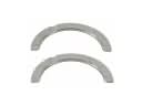 Toyota Tacoma Crankshaft Thrust Washer
 Toyota Tacoma Cylinder Head Gasket
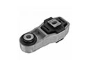 Toyota Tacoma Engine Mount Torque Strut
 Toyota Tacoma Harmonic Balancer
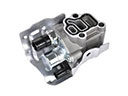 Toyota Tacoma Spool Valve
 Toyota Tacoma Timing Cover
 Toyota Tacoma Timing Idler Gear
Browse Toyota Tacoma Timing Chain by Years
2024 2023 2022 2021 2020 2019 2018 2017 2016 2015 2014 2013 2012 2011 2010 2009 2008 2007 2006 2005 2004 2003 2002 2001 2000 1999 1998 1997 1996 1995