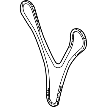
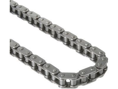
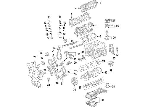
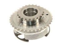
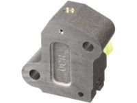
Service of the timing chain system starts by disconnecting the hood sub-assembly on a 2007 Toyota Truck Tacoma 2WD L4-2.7L (2TR-FE) model before discharging fuel system pressure and unfastening No. 1 and No. 2 engine under cover sub-assemblies from 4WD and Pre-Runner models. Service the engine requires draining of oil and coolant before removing the battery tray and battery together. Move toward taking off the radiator support to frame seal LH together with fan shroud, air cleaner cap, filter element and case before separating vane pump assembly without touching hose connections. First disconnect the No. 2 radiator hose followed by disassembly of the magnetic clutch from the compressor and then removal of wires and hoses. Thorough engine assembly removal requires the exhaust pipe assembly together with front exhaust pipe assembly and transmission unit to be taken out first. When changing manual transmission parts the technician must remove clutch cover together with the disc and the flywheel yet automatic transmission maintenance requires removing drive plate and ring gear. Move forward by taking out the rear end plate, intake air connector, generator assembly, V-ribbed belt tensioner assembly and No. 1 idler pulley sub-assembly. When the vehicle comes equipped with an air conditioning system the idle pulley assembly with bracket should be removed first followed by the crankshaft position sensor, camshaft position sensor, No. 1 intake manifold to head gasket and cylinder head cover and crankshaft pulley while the No. 1 cylinder requires positioning at TDC/compression. The technician removes the crankshaft pulley and its bolt by first using Special Service Tool: 09213-54015 (91651-60855), 09330-00021 to loosen the pulley bolt before employing Special Service Tool: 09950-50013 (09951-05010, 09952-05010, 09953-05010, 09954-05021) to detach both components. The maintenance technician should extract the oil level gage sub-assembly and No. 2 oil pan sub-assembly by removing 18 bolts and 2 nuts then carefully sever the sealer application with Special Service Tool: 09032-00100. The service technician should begin by removing the oil strainer sub-assembly and oil pan sub-assembly together with the timing chain cover and timing chain guide and No. 1 chain tensioner assembly. After these components are removed the chain tensioner slipper will be exposed followed by the removal of the No. 1 chain vibration damper, chain sub-assembly, crankshaft timing gear or sprocket and No. 2 and No. 3 chain vibration damper and the No. 2 chain tensioner assembly. The installer should align the No. 2 chain sub-assembly to timing marks before placing the chain tensioner assembly, No. 3 chain vibration damper, No. 2 chain vibration damper together with crankshaft timing gear then adding the No. 1 chain vibration damper followed by chain sub-assembly while making sure timing marks match their painted indicators. Place all installation pieces in sequence that includes the chain tensioner slipper and No. 1 chain tensioner assembly and timing chain guide and timing chain cover. The installation of the oil pan sub-assembly includes seal packing before using its 16 bolts together with two nuts to secure it while completing the installation with an oil strainer sub-assembly. Follow with the No. 2 oil pan sub-assembly, oil level gage sub-assembly, crankshaft pulley, cylinder head cover, No. 1 intake manifold to head gasket, camshaft position sensor, crankshaft position sensor, idle pulley assembly with bracket, No. 1 idler pulley sub-assembly, V-ribbed belt tensioner assembly, generator assembly, intake air connector, rear end plate, drive plate and ring gear sub-assembly for automatic transmission, flywheel sub-assembly, clutch disc assembly, clutch cover assembly, engine assembly, automatic transmission assembly, and manual transmission unit assembly. The exhaust pipe assemblies must be installed next with engine wire connections followed by various hose installations before fitting the compressor and magnetic clutch and sequence with the No. 2 radiator hose, vane pump assembly, air cleaner case, air cleaner filter element, air cleaner cap, fan shroud, radiator support to frame seal LH, battery tray, and battery. Sequence these tasks by adding engine oil and coolant followed by leak tests before installing the hood sub-assembly and its sub-components No. 1 and No. 2.
Posted by ToyotaPartsNow Specialist