×
ToyotaParts- Hello
- Login or Register
- Quick Links
- Live Chat
- Track Order
- Parts Availability
- RMA
- Help Center
- Contact Us
- Shop for
- Toyota Parts
- Scion Parts
My Garage
My Account
Cart
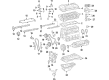
OEM 2009 Toyota Tacoma Timing Chain
Engine Timing Chain- Select Vehicle by Model
- Select Vehicle by VIN
Select Vehicle by Model
orMake
Model
Year
Select Vehicle by VIN
For the most accurate results, select vehicle by your VIN (Vehicle Identification Number).
4 Timing Chains found


2009 Toyota Tacoma Secondary Chain
Part Number: 13507-75030$141.58 MSRP: $200.42You Save: $58.84 (30%)Ships in 1-3 Business DaysProduct Specifications- Other Name: Chain Sub-Assembly; Timing Chain
- Part Name Code: 13507
- Item Weight: 0.70 Pounds
- Item Dimensions: 2.7 x 2.4 x 0.4 inches
- Condition: New
- Fitment Type: Direct Replacement
- SKU: 13507-75030
- Warranty: This genuine part is guaranteed by Toyota's factory warranty.


2009 Toyota Tacoma Secondary Chain
Part Number: 13507-AD010$98.46 MSRP: $138.21You Save: $39.75 (29%)Ships in 1-2 Business DaysProduct Specifications- Other Name: Chain Sub-Assembly; Engine Timing Chain; Chain; Timing Chain
- Manufacturer Note: (L)
- Replaces: 13507-31010
- Part Name Code: 13507
- Item Weight: 0.80 Pounds
- Item Dimensions: 2.7 x 2.5 x 0.4 inches
- Condition: New
- Fitment Type: Direct Replacement
- Require Quantity: 2
- SKU: 13507-AD010
- Warranty: This genuine part is guaranteed by Toyota's factory warranty.


2009 Toyota Tacoma Timing Chain
Part Number: 13506-AD010$264.79 MSRP: $378.07You Save: $113.28 (30%)Ships in 1-3 Business DaysProduct Specifications- Other Name: Chain Sub-Assembly; Engine Timing Chain
- Manufacturer Note: (L)
- Replaces: 13506-31010
- Part Name Code: 13506
- Item Weight: 1.90 Pounds
- Item Dimensions: 6.4 x 3.5 x 1.2 inches
- Condition: New
- Fitment Type: Direct Replacement
- SKU: 13506-AD010
- Warranty: This genuine part is guaranteed by Toyota's factory warranty.

2009 Toyota Tacoma Timing Chain
Part Number: 13506-75070$247.20 MSRP: $352.95You Save: $105.75 (30%)Ships in 1-3 Business DaysProduct Specifications- Other Name: Chain Sub-Assembly; Engine Timing Chain
- Replaces: 13506-75050, 13506-0C040
- Part Name Code: 13506
- Item Weight: 1.50 Pounds
- Item Dimensions: 6.8 x 3.5 x 1.4 inches
- Condition: New
- Fitment Type: Direct Replacement
- SKU: 13506-75070
- Warranty: This genuine part is guaranteed by Toyota's factory warranty.
2009 Toyota Tacoma Timing Chain
Looking for affordable OEM 2009 Toyota Tacoma Timing Chain? Explore our comprehensive catalogue of genuine 2009 Toyota Tacoma Timing Chain. All our parts are covered by the manufacturer's warranty. Plus, our straightforward return policy and speedy delivery service ensure an unparalleled shopping experience. We look forward to your visit!
2009 Toyota Tacoma Timing Chain Parts Q&A
- Q: How to install the No. 2 Timing Chain sub-assembly and complete the assembly process on 2009 Toyota Tacoma?A: The installation of the No. 2 chain sub-assembly requires correct placement of the marked chain links to match the timing marks on crankshaft timing sprockets and balance shaft timing sprockets. It is necessary to position the marked link of the crankshaft timing sprocket behind the large timing mark of the balance shaft drive gear. The balance shaft drive gear shaft requires insertion into the thrust plate hole with the small timing mark of the balance shaft drive gear perfectly aligned to the balance shaft timing gear timing mark before tightening the bolt to 25 Nm (250 kgf-cm, 18 ft-lbf). Check that every timing mark has achieved its correct alignment. The installation includes No. 2 chain tensioner assembly with its nut tightened to 18 Nm (185 kgf-cm, 13 ft-lbf) under a condition where a 3.0 mm (0.118 in.) diameter bar must be used for chain assembly before removal (the bar should not engage with the vibration damper). Fasten the two bolts securing No. 3 chain vibration damper to 18 Nm then apply the same torque to No. 2 chain vibration damper before pulling the pin from the chain tensioner to decompress the plunger. Welcome the crankshaft timing gear or sprocket as the instructions show and mount the No. 1 chain vibration damper using a bolt and nut that requires 21 Nm (214 kgf-cm, 15 ft-lbf) tightening torque. The crankshaft timing sprocket chain must be secured with a rope to stop gear jumping before removing the tether when installing the chain tensioner. Fasten the bolt on the chain tensioner slipper to 21 Nm (214 kgf-cm, 15 ft-lbf) torque and subsequently add the No. 1 chain tensioner assembly with new gasket using a bolt and nut at 10 Nm (102 kgf-cm, 7 ft-lbf). Place the timing chain guide together with its O-ring and fasten it with two bolts at 10 Nm torque (102 kgf-cm / 7 ft-lbf). Following this, attach the timing chain cover. The Toyota Genuine Seal Packing Black or Three Bond 1207B or equivalent should be used to form continuous beads with a 2 to 3 mm (0.079 to 0.118 in.) seal width for the oil pan sub-assembly before installing the crankcase within 3 minutes and waiting at least 2 hours before starting the engine. Insert the oil pan with its 16 bolts and 2 nuts but do not fully tighten until reaching 26 Nm (265 kgf-cm, 19 ft-lbf). Fasten the oil strainer sub-assembly with new gasket through its 2 bolts and 2 nuts until torque reaches 26 Nm (265 kgf-cm, 19 ft-lbf). Install the No. 2 oil pan sub-assembly with continuous beads of seal packing sized at 3 to 4 mm (0.118 to 0.157 in.) but keep the crankcase inside 3 minutes which requires at least 2 hours without engine startup. Fitting the oil pan first requires temporary bolt placement along with two nuts before applying uniform tension to 9.0 Nm (92 kgf-cm, 80 in-lbf) for installation of a new gasket along with the drain plug. Continue with the installation of the oil level gage sub-assembly, crankshaft pulley, cylinder head cover sub-assembly, No. 1 intake manifold to head gasket, camshaft position sensor, crankshaft position sensor, idle pulley assembly with bracket (if equipped with air conditioning), No. 1 idler pulley sub-assembly tightened to 43 Nm (438 kgf-cm, 32 ft-lbf), V-ribbed belt tensioner assembly, generator assembly, intake air connector, rear end plate with 2 bolts tightened to 18 Nm (184 kgf-cm, 13 ft-lbf), drive plate and ring gear sub-assembly (for automatic transmission), flywheel sub-assembly (for manual transmission), clutch disc assembly (for manual transmission), clutch cover assembly (for manual transmission), engine assembly, automatic transmission assembly, manual transmission unit assembly, exhaust pipe assembly front, exhaust pipe assembly tail, engine wire connection, No. 1 air injection hose connection, fuel vapor feed hose assembly connection, No. 2 fuel hose connection, fuel hose connection, water hose sub-assembly installation, radiator hose inlet installation, compressor and magnetic clutch (if equipped with air conditioning) tightened to 21 Nm (214 kgf-cm, 16 ft-lbf) and connecting the compressor and magnetic clutch connector, followed by the installation of the bolt shown in the illustration tightened to 7.5 Nm (76 kgf-cm, 66 in-lbf), No. 2 radiator hose installation, vane pump assembly installation with 2 bolts tightened to 21 Nm (214 kgf-cm, 16 ft-lbf) and connecting the vane pump connector, air cleaner case installation with 3 bolts tightened to 12 Nm (122 kgf-cm, 9 ft-lbf), air cleaner filter element sub-assembly installation, air cleaner cap sub-assembly installation, fan shroud installation, radiator support to frame seal LH installation, battery tray installation, battery installation, adding engine oil, adding engine coolant, checking for engine oil level, checking for fuel leakage, checking for engine coolant leakage, checking for oil leakage, checking for exhaust gas leakage, No. 1 engine under cover sub-assembly installation (for 4WD and Pre-Runner) with 4 bolts tightened to 30 Nm (306 kgf-cm, 22 ft-lbf), No. 2 engine under cover sub-assembly installation (for 4WD and Pre-Runner, Regular Cab) with 4 bolts tightened to 30 Nm (306 kgf-cm, 22 ft-lbf), and hood sub-assembly installation.
Related 2009 Toyota Tacoma Parts
 2009 Toyota Tacoma Dipstick
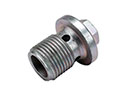 2009 Toyota Tacoma Drain Plug
 2009 Toyota Tacoma Valve Cover Gasket
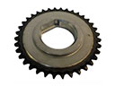 2009 Toyota Tacoma Balance Shaft Gear
 2009 Toyota Tacoma Dipstick Tube
 2009 Toyota Tacoma Drain Plug Washer
 2009 Toyota Tacoma Engine Mount
 2009 Toyota Tacoma Exhaust Valve
 2009 Toyota Tacoma Intake Valve
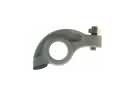 2009 Toyota Tacoma Rocker Arm
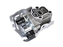 2009 Toyota Tacoma Spool Valve
 2009 Toyota Tacoma Valve Stem Seal