×
ToyotaParts- Hello
- Login or Register
- Quick Links
- Live Chat
- Track Order
- Parts Availability
- RMA
- Help Center
- Contact Us
- Shop for
- Toyota Parts
- Scion Parts
My Garage
My Account
Cart
OEM Toyota Solara Camshaft
Cam- Select Vehicle by Model
- Select Vehicle by VIN
Select Vehicle by Model
orMake
Model
Year
Select Vehicle by VIN
For the most accurate results, select vehicle by your VIN (Vehicle Identification Number).
8 Camshafts found


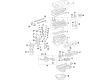
Toyota Solara Camshaft Part Number: 13501-28060
$343.78 MSRP: $503.81You Save: $160.03 (32%)
Toyota Solara Camshaft Part Number: 13502-28010
$356.95 MSRP: $523.11You Save: $166.16 (32%)Ships in 1-3 Business Days
Toyota Solara Camshaft Part Number: 13502-20030
$301.02 MSRP: $429.79You Save: $128.77 (30%)Ships in 1-3 Business Days
Toyota Solara Camshaft Part Number: 13502-28030
$323.51 MSRP: $461.90You Save: $138.39 (30%)Ships in 1-3 Business Days
Toyota Solara Camshaft Sub-Assembly Part Number: 13053-20040
$340.17 MSRP: $485.68You Save: $145.51 (30%)Ships in 1-3 Business Days
Toyota Solara Camshaft Part Number: 13501-28040
$359.22 MSRP: $526.44You Save: $167.22 (32%)
Toyota Solara Camshaft Sub-Assembly Part Number: 13054-20030
$316.17 MSRP: $451.42You Save: $135.25 (30%)Toyota Solara Camshaft Part Number: 13501-20050
$340.17 MSRP: $485.68You Save: $145.51 (30%)
Toyota Solara Camshaft
Choose genuine Camshaft that pass strict quality control tests. You can trust the top quality and lasting durability. Shopping for OEM Camshaft for your Toyota Solara? Our website is your one-stop destination. We stock an extensive selection of genuine Toyota Solara parts. The price is affordable so you can save more. It only takes minutes to browse and find the exact fit. Easily add to cart and check out fast. Our hassle-free return policy will keep you stress-free. We process orders quickly for swift delivery. Your parts will arrive faster, so you can get back on the road sooner.
Camshaft in Toyota Solara cars is involved in managing the intake and exhaust valves; consequently, the crank of air and fuel into the chamber for burning. All these camshafts can be block mounted or cylinder head mounted and come with many combinations including OHV, SOHC, and DOHC engines. Valves are timed with the aid of the camshaft which is in turn timed with the crankshaft. Such parts as performance camshafts can be of real value to Solara owners who are in need of a boost in power and efficiency of their vehicle. These are performance camshafts of higher lift and duration that enhance the airflow and also the power output. Some of the aspects that may influence the kind of camshaft required include the desired compression ratio, kind of transmission system, weight of the car among others. Moreover, the angle at which the camshaft is split into lobes can also affect torque, the RPM range as well as the quality of idling.
Toyota Solara Camshaft Parts and Q&A
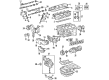
- Q: How to Install the Camshaft Timing Gear Assembly, Timing Chain, Tensioner, and Cylinder Head Cover During Camshaft Installation on Toyota Solara?A:Install the camshaft timing gear assembly by putting it in position next to the camshaft and perform a gentle turning motion according to directions until the pin meets the groove while maintaining awareness of not flexing towards the retarded angle area. Next, verify the gear fringe does not create any space with the camshaft before fastening the bolt with 54 Nm torque (551 kgc-m, 40 ft-lbf). Make sure the camshaft timing gear can proceed to the extreme retarded angle and maintain this position. First place the Timing Chain on the camshaft timing gear, position the painted link mark to the timing marks. Then install the bearing caps correctly while torquing bearing cap Number 1 to 30 Nm (301 kgf-cm, 22 ft-lbf) and bearing cap Number 3 to 9.0 Nm (92 kgf-cm, 80 in-lbf). To set the No.2 camshaft properly install the bearing caps by screwing bearing cap No.2 to 30 Nm (301 kgf-cm, 22 ft-lbf) and bearing cap No.3 to 9.0 Nm (92 kgf-cm, 80 in-lbf) while also tightening the sprocket bolt to 54 Nm (551 kgf-cm, 40 ft-lbf) since the valve lifter remains sensitive during this operation. Check the correct alignment between paint marks which should be present on the timing chain, camshaft timing gear, camshaft timing sprocket, and the pulley groove which should face the timing mark of the chain cover. When installing the No.1 chain tensioner assembly first raise the ratchet pawl and push the plunger before securing it with the hook while adding new gasket material and securing the chain tensioner and its two nuts to 9.0 Nm (92 kgf-cm, 80 in-lbf). Turn the crankshaft counterclockwise first so the plunger knock pin separates from the hook and then clock-wise to confirm the slipper is pushed by the plunger. Apply Toyota Genuine Adhesive 1344 or Three Bond 1344 or their equivalent at the specified cover locations after cleaning the contact surfaces of all oil residue and install the cover time-wise within five minutes while keeping the engine oil away from touching the parts for more than 2 hours post-assembling. Install and fasten the cylinder head cover with its combination of 8 bolts and 2 nuts by applying 11 Nm (110 kgf-cm, 8 ft-lbf) torque. The engine wire needs connection for the installation of the spark plug at 19 Nm torque (194 kgf-cm or 14 ft-lbf) followed by front wheel RH mounting then checking for oil leaks.
- Q: How to remove the camshaft on Toyota Solara?A:The first step to remove the camshaft from the 2AZ-FE engine includes disconnecting the front wheel RH and both front fender apron seal RH as well as engine cover sub-assembly No.1, spark plug and ventilation hose and ventilation hose No.2 and engine wire. The procedure starts with removing the bolt from the cylinder head cover sub-assembly but before moving on you need to disconnect the engine wire harness clamp followed by removing the bolts along with the two nuts which is required to separate the cylinder head cover and gasket. Place paint marks on the Timing Chain after aligning its groove with the timing mark 0 of the timing chain cover by turning the crankshaft pulley to TDC/compression. The procedure requires removing the No.1 chain tensioner assembly by unfastening its 2 nuts while keeping in mind to never rotate the crankshaft bare without the tensioner present. Begin with wrenches to secure the No.2 camshaft before loosening the bolt and then removing the bearing cap bolts in particular order to take off five caps to raise the No.2 camshaft along with the removal of its sprocket bolt. The camshaft timing sprocket combination with the timing chain must be disconnected from the No.2 camshaft before sprocket separation from the timing chain occurs. When performing camshaft removal it becomes essential to loosen bearing cap bolts according to the specified sequence while removing caps until the camshaft can be removed. The timing chain should be secured with a string to avoid dropping any components into the timing chain cover. To operate the camshaft timing gear assembly researchers should place the No.1 camshaft inside a vise to stop rotation before applying vinyl tape over every path except the advanced path. They should then use compressed air at 150 kPa (1.5 kgf/cm, 21 psi) through the advanced port and wipe away any oil with a shop rag. Inspection must confirm free hand movement of the camshaft timing gear toward its advanced angle side. The fringe bolt on the camshaft timing gear requires removal but other 4 bolts should remain intact for reuse if planning to reinstall the gear. Initially free the straight pin lock before reinstalling the timing gear.


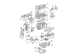
Related Toyota Solara Parts
 Toyota Solara Oil Pump
 Toyota Solara Cam Gear
 Toyota Solara Crankshaft Gear
 Toyota Solara Cylinder Head
 Toyota Solara Dipstick
 Toyota Solara Dipstick Tube
 Toyota Solara Intake Valve
 Toyota Solara Rod Bearing
 Toyota Solara Timing Chain Tensioner
 Toyota Solara Timing Cover
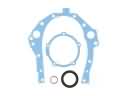 Toyota Solara Timing Cover Gasket
 Toyota Solara Valve Stem Seal