×
ToyotaParts- Hello
- Login or Register
- Quick Links
- Live Chat
- Track Order
- Parts Availability
- RMA
- Help Center
- Contact Us
- Shop for
- Toyota Parts
- Scion Parts
My Garage
My Account
Cart
OEM Toyota Solara Timing Chain
Engine Timing Chain- Select Vehicle by Model
- Select Vehicle by VIN
Select Vehicle by Model
orMake
Model
Year
Select Vehicle by VIN
For the most accurate results, select vehicle by your VIN (Vehicle Identification Number).
2 Timing Chains found


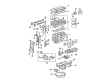
Toyota Solara Timing Chain Part Number: 13507-28010
$92.18 MSRP: $129.39You Save: $37.21 (29%)Ships in 1-2 Business Days

Toyota Solara Timing Chain Part Number: 13506-0H011
$268.87 MSRP: $383.89You Save: $115.02 (30%)Ships in 1-2 Business Days
Toyota Solara Timing Chain
Choose genuine Timing Chain that pass strict quality control tests. You can trust the top quality and lasting durability. Shopping for OEM Timing Chain for your Toyota Solara? Our website is your one-stop destination. We stock an extensive selection of genuine Toyota Solara parts. The price is affordable so you can save more. It only takes minutes to browse and find the exact fit. Easily add to cart and check out fast. Our hassle-free return policy will keep you stress-free. We process orders quickly for swift delivery. Your parts will arrive faster, so you can get back on the road sooner.
A Timing Chain is fitted in Toyota Solara vehicles to co-ordinate the rotation of the camshaft and crankshaft to maintain correct valve timing for prime engine performance. Found in front of the engine, this metal chain used for operating the gears needs lubrication and is conventional in higher displacements. Metal timing chains have lately gained the preference over rubber timing belts particularly since the 90s due to their strength and the reduced frequency of exchange. Timing chains are in general uncomplicated but they sometimes yield problems which are due to lubrication failure or problems regarding the tensioner and chaining guides; the manifestation of this would be a rattling sound emanating from the front of the engine. A short chain drive is desirable in pushrod engines due to noise and wear consideration; it can thus fit well in the Solara's engines.
Toyota Solara Timing Chain Parts and Q&A
- Q: How to remove the timing chain on Toyota Solara?A:Begin by uninstalling the hood sub-assembly followed by the front wheel RH and then removing both engine under covers LH and RH together with the front fender apron seal RH. The engine oil requires drainage followed by new gasket installation before securing the drain plug at 25 Nm torque (255 kgf-cm, 18 ft-lbf). Remove the front Exhaust Pipe assembly followed by the engine moving control rod with bracket then the engine mounting stay No.2 RH along with the engine mounting bracket No.2 RH. Proceed with the removal of the fan and generator V belt and then follow with the sequence of taking out the No.1 engine cover sub-assembly and engine wire and generator assembly and vane pump assembly and Ignition Coil assembly and lastly disconnect the ventilation hoses. Seamlessly disconnect the engine wire harness clamp from the cylinder head cover sub-assembly following removal of 8 bolts and 2 nuts. The repair technician should start by positioning the No.1 cylinder at TDC/compression before using Special Service Tools 09960-10010 and 09962-01000 to fix the pulley followed by loosening the bolt and completing its removal with Special Service Tools 09950-40011, 09951-04010, 09952-04010, 09953-04030, 09954-04010, 09955-04041, 09957-04010 and 91111-51014. Before separation cut the sealer between oil pan and crankcase with an oil pan seal cutter while removing 12 bolts and 2 nuts from the Crankshaft Position Sensor and oil pan sub-assembly. The crankshaft should stay stationary when you uninstall No.1 chain tensioner assembly. Proceed to uninstall the bolt and nut and tensioner component from the V-ribbed belt tensioner assembly regardless of spring inclusion. Attach the engine hangers No. 1 and No. 2 with bolts that reach 38 Nm (387 kgf-cm, 28 ft-lbf) torque specification before connecting the engine chain hoist to the hangers. The first step requires removal of the bolt to disconnect FR from the engine mounting insulator. Next disconnect the manual transmission engine lateral control rod by removing the bolt. A steering gear return hose clamp must also be disconnected from the frame. Raising the engine becomes possible after you remove the 4 nuts from around the engine mounting insulator RH. The engine mounting bracket RH must be removed after removing 3 bolts, followed by timing chain cover sub-assembly extraction. With proper tooling remove the crankshaft position sensor plate No.1 and each of the chain tensioner slipper and chain vibration damper No.1, timing chain guide and bolts. Extract the combination of chain components along with the crankshaft timing sprocket. The maintenance of the No.2 chain sub-assembly requires counter-clockwise crankshaft rotation by 90 degrees followed by alignment of the oil pump driven sprocket adjusting hole with the pump groove and securement with a 4 mm (0.16 in.) bar prior to removing the nut, bolt, chain tensioner plate, spring, chain tensioner and oil pump driven sprocket, and chain.
- Q: How to install the No.2 Timing Chain sub-assembly on Toyota Solara?A:Before installing the 2AZ-FE No.2 chain sub-assembly you must place the crankshaft key in its left horizontal orientation then turn the oil pump drive shaft cutout to its upper platform. Fasten the oil pump driven sprocket with the nut after setting it into position using a 4 mm (0.16 in.) bar. Apply torque to 30 Nm (301 kgf-cm, 22 ft-lbf), then lock it temporarily by tightening the nut on the oil pump driven sprocket. To align the crankshaft key at the top position turn it counterclockwise by 90 degrees. Two bolts should be installed on the crankshaft sprocket while using 9.0 Nm (92 kgf-cm, 80 in-lbf) torque to secure the chain vibration damper. Set the No.1 cylinder at TDC/compression alignment by placing the timing marks from the camshaft timing gear/sprocket and bearing caps together and using Special Service Tool: 09309-37010 to align the gold or orange mark link to the crankshaft timing sprocket timing mark for sprocket insertion. Fasten the timing chain guide under 9.0 Nm (92 kgf-cm, 80 in-lbf) and the chain tensioner slipper with 19 Nm (194 kgf-cm, 14 ft-lbf). Installation of the Crankshaft Position Sensor plate begins with setting its F mark toward the front and then placing the timing chain cover sub-assembly. The V-ribbed belt tensioner assembly installation requires bolt and nut tightening to reach 60 Nm (607 kgf-cm, 44 ft-lbf), but keep the pin out of the unit if you replace it with new hardware. You should raise the engine to install its engine mounting insulator RH by torquing Nut A to 95 Nm (969 kgf-cm, 70 ft-lbf) and Nut B to 87 Nm (888 kgf-cm, 64 ft-lbf). The installation of the steering gear return hose clamp to the frame requires a bolt torque of 8.0 Nm (80 kgf-cm, 69 in-lbf) while the engine mounting insulator FR needs a bolt torque of 87 Nm (888 kgf-cm, 64 ft-lbf). The manual transmission engine lateral control rod must be secured with a bolt achieving 89 Nm of torque (910 kgf-cm, 66 ft-lbf). The installation of the oil pan requires 12 bolts and two nuts which need tightness to 9.0 Nm (92 kgf-cm, 80 in-lbf) while applying seal packing of 4 to 4.5 mm (0.16 to 0.18 in.) diameter in one continuous bead. Following the crankshaft position sensor installation apply the correct wire harness positioning and install the No.1 chain tensioner assembly first before bolting the sensor down with 9.0 Nm (92 kgf-cm, 80 in-lbf). Secure the crankshaft pulley using Special Service Tool: 09960-10010, 09962-01000, 09963-01000 while aligning the pulley set key against the key groove then torque the pulley bolt to 180 Nm (1836 kgf-cm, 135 ft-lbf). You should turn the crankshaft counterclockwise to remove the plunger knock pin before testing that the plunger pushes the slipper by turning the crankshaft clockwise. The cylinder head cover sub-assembly can be installed along with the Ignition Coil assembly which requires a torque setting of 9.0 Nm (92 kgf-cm, 80 in-lbf) and the vane pump assembly. Install the generator assembly and engine wire while using Service Tool: 09249-63010 to achieve proper tensioning of the v-belt alongside the fan. As the final steps install the engine mounting bracket No.2 RH with 52 Nm torques (531 kgf-cm, 38 ft-lbf) and the matching engine mounting stay No.2 RH torqued to 64 Nm (653 kgf-cm, 47 ft-lbf) before proceeding to attach the engine moving control rod with 3 bolts torqued to 64 Nm (653 kgf-cm, 47 ft-lbf), followed by the front Exhaust Pipe assembly, front wheel RH, hood sub-assembly torqued to 13 Nm (133 kgf-cm, 10 ft-lbf), add engine oil, and inspect for oil leaks.


Related Toyota Solara Parts
 Toyota Solara Oil Filter
 Toyota Solara Timing Belt
 Toyota Solara Cam Gear
 Toyota Solara Camshaft
 Toyota Solara Camshaft Bearing
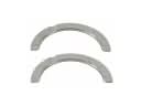 Toyota Solara Crankshaft Thrust Washer
 Toyota Solara Dipstick
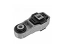 Toyota Solara Engine Mount Torque Strut
 Toyota Solara Piston
 Toyota Solara Piston Ring Set
 Toyota Solara Timing Chain Tensioner
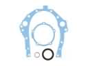 Toyota Solara Timing Cover Gasket