×
ToyotaParts- Hello
- Login or Register
- Quick Links
- Live Chat
- Track Order
- Parts Availability
- RMA
- Help Center
- Contact Us
- Shop for
- Toyota Parts
- Scion Parts
My Garage
My Account
Cart
OEM Toyota Solara Timing Belt
Engine Timing Belt- Select Vehicle by Model
- Select Vehicle by VIN
Select Vehicle by Model
orMake
Model
Year
Select Vehicle by VIN
For the most accurate results, select vehicle by your VIN (Vehicle Identification Number).
2 Timing Belts found


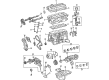
Toyota Solara Timing Belt Part Number: 13568-09041
$44.44 MSRP: $61.86You Save: $17.42 (29%)Ships in 1-3 Business Days


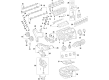
Toyota Solara Timing Belt Part Number: 13568-09080
$60.54 MSRP: $84.98You Save: $24.44 (29%)Ships in 1-2 Business Days
Toyota Solara Timing Belt
Choose genuine Timing Belt that pass strict quality control tests. You can trust the top quality and lasting durability. Shopping for OEM Timing Belt for your Toyota Solara? Our website is your one-stop destination. We stock an extensive selection of genuine Toyota Solara parts. The price is affordable so you can save more. It only takes minutes to browse and find the exact fit. Easily add to cart and check out fast. Our hassle-free return policy will keep you stress-free. We process orders quickly for swift delivery. Your parts will arrive faster, so you can get back on the road sooner.
In the case of a Toyota Solara, the Timing Belt is responsible for the proper operation of the crankshaft and camshaft so that the engine valves open and shut at optimal times. These belts are usually of rubber and contain fibers; their advantages include lower cost, creation of less friction, and are less noisy as compared to gear or chain operations. But like many other humble devices in the world, they need replacement after sometimes due to wear and tear. Contemporary crankshaft pulleys with curved teeth are less noisy and less susceptible to wear, preaching not only the crankshaft and camshaft but also such parts as water and oil pumps. Timing belts have been fitted in Solara models for some years hence there has been the use of different kinds of timing belts and a switch in material and design makes these belts to have a better performance and a longer life period.
Toyota Solara Timing Belt Parts and Q&A
- Q: How to remove and install the timing belt on Toyota Solara?A:The first step for timing belt removal requires unwinding both bolts to detach the RH front wheel with its suspension upper brace and RH fender apron seal plus the generator Drive Belt and PS pump drive belt. Disconnect the engine coolant reservoir hose which is attached to the water outlet as well as the ground strap connectors. First detach the No.2 RH engine mounting bracket through generator pivot bolt loosening and removing its nut and bracket. Then take out the No.2 RH engine mounting stay, engine moving control rod, and RH engine mounting stay following the engine mounting stay removal. Use Special Service Tool: 09213-54015 (91651-60855) together with 09330-00021 to detach the crankshaft pulley bolt before utilizing Special Service Tool: 09950-50012 (09951-05010, 09952-05010, 09953-05010, 09953-05020, 09954-05020) to remove the pulley. Start by removing the 4 bolts from the No.1 timing belt cover before taking out the timing belt guide and finishing with removal of the 5 bolts from the No.2 timing belt cover after engine wire protector clamps have been disconnected. The removal of RH engine mounting bracket requires disassembly of its two bolts together with the accompanying nut. Use a crankshaft pulley bolt and checking procedure to establish No.1 cylinder at TDC/compression. Then check Camshaft timing pulley and No.3 timing belt cover alignment. Verify the presence of three installation marks and a front mark on the timing belt before removal because no marks indicate a need for new placement. Use Special Service Tool: 09249-63010, 09960-10010 (09962-01000, 09963-01000) for the RH timing pulley and Special Service Tool: 09960-10010 (09962-01000, 09963-01000) for the LH timing pulley while removing the camshaft timing pulleys after draining the timing belt tensioner and its two bolts in alternating techniques. Use a 10 mm hexagon wrench to uninstall the No.2 idler pulley followed by the No.1 idler pulley from the vehicle. Move the crankshaft timing pulley off its bolt and timing belt plate yet proceed to extract it through Special Service Tool: 09950-50012 (09951-05010, 09952-05010, 09953-05010, 09953-05020, 09954-05010) while being careful to prevent damage to the sensor region. Check the timing belt for proper condition among defects and verify its resistance to bending and twisting as well as its compatibility with oil, water, and steam exposure and confirm correct installation and wear levels. The staff should check idler pulleys for oil leakage while inspecting the pulleys' smooth operation and examining the timing belt tensioner for oil leakage and proper push rod movement. Position the crankshaft timing pulley by matching the pulley set key with the key groove followed by pulley insertion. Then install the timing belt plate together with its bolt. Add adhesive Part No. 08833-00080 such as Three Bond 1344 or Loctite 242 or equivalent to the No.1 idler pulley installation before proceeding with the No.2 idler pulley. Use the correct Special Service Tool to position the RH camshaft timing pulley with the flange facing outward while you place the LH pulley inside with its flange on the inner side. Verify that all timing marks coincide when you position the No.1 cylinder at TDC/compression. Mount the belt to the engine when it is cool and with clean pulleys by following specific installation order. Set the timing belt tensioner by activating the push rod for pressing and securing it with a hexagon wrench. Afterward, install the timing belt tensioner and verify valve timing alignment by cranking the crankshaft and checking all timing marks. The necessary installation steps involve placing the RH engine mounting bracket and the No.2 timing belt cover, timing belt guide, No.1 timing belt cover, and crankshaft pulley with attention to using suitable gaskets that are both functional and correctly positioned. The final stage involves installing the No.2 generator bracket, No.2 RH engine mounting bracket, engine moving control rod followed by No.2 RH engine mounting stay (M/T) and RH engine mounting stay and reattaching the ground strap connectors and engine coolant reservoir hose and PS pump drive belt, generator drive belt, RH fender apron seal, and RH front wheel with the suspension upper brace finally installed before conducting a road test evaluation of abnormal noise, shock, slippage, correct shift points, and smooth operation.

Related Toyota Solara Parts
 Toyota Solara Valve Cover Gasket
 Toyota Solara Harmonic Balancer
 Toyota Solara Crankshaft Pulley
 Toyota Solara Crankshaft Seal
 Toyota Solara Cylinder Head Gasket
 Toyota Solara Dipstick
 Toyota Solara Dipstick Tube
 Toyota Solara Oil Pan
 Toyota Solara Piston
 Toyota Solara Piston Ring Set
 Toyota Solara Timing Chain
 Toyota Solara Timing Chain Guide