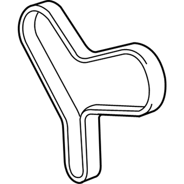
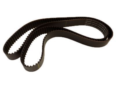
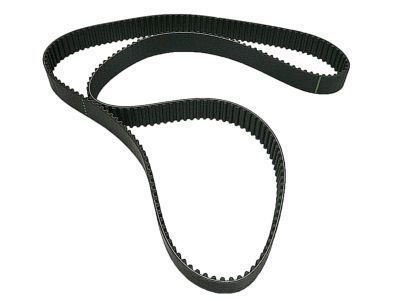
OEM Toyota part with Part Number 13568-09080 Timing Belt known as Toyota Timing Belt component provides maximum durability and optimal performance. The certified Toyota dealership components feature a warranty protection for 12-month, 12,000-mile usage. The use of OEM part 13568-09080 Timing Belt enables maintenance standards that match the original factory installation quality. The specific item serves the following model series: 1994-2006 Toyota Camry and 2001-2010 Toyota Highlander and 1998-2006 Toyota Sienna as well as 1995-2004 Toyota Avalon.
Genuine Toyota offers this high-quality Belt, Timing; Engine Timing Belt; Timing Belt Kit under Manufacturer Part Number 13568-09080 for use. This product identification code consists of 13568 which proves its manufacturer as Toyota. This component features dimensions of 14.0 x 12.1 x 2.1 inches and weighs 1.00 Pounds. This component 1356809080 is specially constructed for vehicle fitting requirements within the Direct Replacement classification. This product could replace 13568-09050. Each vehicle requires the component which has an identified SKU of 13568-09080. The factory-warranty from Toyota guarantees continuous reliable operation and high performance for this part 13568-09080. The Shipping Policy and Return Policy pages provide full details about shipping procedures and return instructions.
OEM parts have no match as far as quality is concerned. They are thoroughly quality controlled and are made to Toyota factory specifications. All these eliminate the faults and flaws. And that is why you can be worry-free because they guarantee an outstanding lifespan and perfect matching. We offer very many different OEM components at competitive prices at ToyotaPartsNow.com. We offer an entire product line of all authentic Toyota products, with a manufacturer warranty as an assurance. Customer satisfaction is also part of our priorities and we offer no-hassles returns and fast shipping of all our components.
