×
ToyotaParts- Hello
- Login or Register
- Quick Links
- Live Chat
- Track Order
- Parts Availability
- RMA
- Help Center
- Contact Us
- Shop for
- Toyota Parts
- Scion Parts
My Garage
My Account
Cart
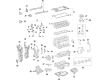
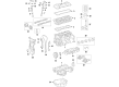
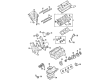
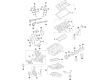
OEM Toyota Highlander Camshaft
Cam- Select Vehicle by Model
- Select Vehicle by VIN
Select Vehicle by Model
orMake
Model
Year
Select Vehicle by VIN
For the most accurate results, select vehicle by your VIN (Vehicle Identification Number).
36 Camshafts found

Toyota Highlander Camshaft Part Number: 13501-31110
$622.42 MSRP: $912.17You Save: $289.75 (32%)Ships in 1-3 Business Days
Toyota Highlander Camshaft Sub-Assembly Part Number: 13054-31070
$604.23 MSRP: $885.50You Save: $281.27 (32%)Ships in 1-3 Business Days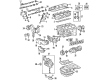
Toyota Highlander Camshaft Part Number: 13501-20060
$301.02 MSRP: $429.79You Save: $128.77 (30%)Ships in 1-3 Business Days
Toyota Highlander Camshaft Part Number: 13502-28020
$309.88 MSRP: $442.44You Save: $132.56 (30%)Ships in 1-3 Business Days

Toyota Highlander Camshaft Part Number: 13502-F0080
$344.69 MSRP: $505.14You Save: $160.45 (32%)Ships in 1-2 Business DaysToyota Highlander Camshaft Sub-Assembly, Intake Part Number: 13501-F0080
$344.69 MSRP: $505.14You Save: $160.45 (32%)Ships in 1-2 Business Days
Toyota Highlander Camshaft Part Number: 13502-28010
$356.95 MSRP: $523.11You Save: $166.16 (32%)Ships in 1-3 Business Days
Toyota Highlander Camshaft Part Number: 13501-28010
$359.56 MSRP: $526.93You Save: $167.37 (32%)Ships in 1-3 Business Days
Toyota Highlander Camshaft Part Number: 13502-F0020
$362.05 MSRP: $530.60You Save: $168.55 (32%)Ships in 1-3 Business Days
Toyota Highlander Camshaft Part Number: 13501-F0030
$362.05 MSRP: $530.60You Save: $168.55 (32%)Ships in 1-3 Business Days
Toyota Highlander Camshaft Part Number: 13502-36030
$372.95 MSRP: $546.56You Save: $173.61 (32%)Ships in 1-3 Business Days
Toyota Highlander Camshaft Part Number: 13501-36050
$383.28 MSRP: $561.70You Save: $178.42 (32%)Ships in 1-3 Business Days
Toyota Highlander Camshaft Part Number: 13502-31061
$541.61 MSRP: $793.74You Save: $252.13 (32%)Ships in 1-3 Business Days
Toyota Highlander Camshaft Part Number: 13501-31091
$537.30 MSRP: $787.41You Save: $250.11 (32%)Ships in 1-3 Business DaysToyota Highlander Camshaft Sub-Assembly Part Number: 13054-31061
$533.55 MSRP: $781.93You Save: $248.38 (32%)Ships in 1-3 Business Days
Toyota Highlander Camshaft Part Number: 13053-31061
$541.61 MSRP: $793.74You Save: $252.13 (32%)Ships in 1-3 Business Days
Toyota Highlander Camshaft Part Number: 13502-31070
$546.09 MSRP: $800.31You Save: $254.22 (32%)Ships in 1-3 Business Days
Toyota Highlander Camshaft Sub-Assembly Part Number: 13502-31110
$548.42 MSRP: $803.72You Save: $255.30 (32%)Ships in 1-3 Business Days
Toyota Highlander Camshaft Sub-Assembly Part Number: 13501-31140
$548.42 MSRP: $803.72You Save: $255.30 (32%)Ships in 1-3 Business Days
Toyota Highlander Camshaft Part Number: 13501-28040
$359.22 MSRP: $526.44You Save: $167.22 (32%)
| Page 1 of 2 |Next >
1-20 of 36 Results
Toyota Highlander Camshaft
Choose genuine Camshaft that pass strict quality control tests. You can trust the top quality and lasting durability. Shopping for OEM Camshaft for your Toyota Highlander? Our website is your one-stop destination. We stock an extensive selection of genuine Toyota Highlander parts. The price is affordable so you can save more. It only takes minutes to browse and find the exact fit. Easily add to cart and check out fast. Our hassle-free return policy will keep you stress-free. We process orders quickly for swift delivery. Your parts will arrive faster, so you can get back on the road sooner.
Toyota Highlander Camshaft Parts and Q&A
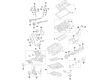
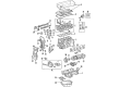
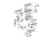
- Q: How is the Camshaft Installed on Toyota Highlander?A:Begin the camshaft installation of the 2GR-FE engine by applying oil to camshaft journals and camshaft bearing caps together with camshaft housing sub-assembly LH. Afterward, insert the No. 3 and No. 4 camshafts into the camshaft housing sub-assembly LH using the correct alignment of marks with numbers on the camshaft bearing caps. Secure the 8 bolts temporarily by torquing them to 10 Nm (102 kgf-cm, 7 ft-lbf). Install the camshaft sub-assembly LH while applying Toyota Genuine Seal Packing Black, Three Bond 1207B or equivalent. Use a continuous line with a 3.5 to 4.5 mm (0.138 to 0.177 in.) diameter seal. Then tighten each of the 13 bolts to 28 Nm (286 kgf-cm, 21 ft-lbf). The camshafts must be perfectly aligned to prevent piston and valve contact while any loose bolts require cleaning their surfaces before reinstallation of new seal packing. Tighten the 8 bolts to reach a torque value of 16 Nm (163 kgf-cm) equivalent to 12 ft-lbf. Fasten the No. 3 chain tensioner using a torque of 21 Nm (214 kgf-cm, 15 ft-lbf) while securing it with a 1.0 mm (0.039 in.) diameter pin. Apply engine oil to bolt threads and seating surface of the mark plate before mounting the camshaft timing gear assembly and camshaft timing exhaust gear LH with the No. 2 chain sub-assembly. Align the yellow mark plate with the 2-dot mark of the camshaft timing gear assemblies. Install the components by starting with the 2-dot mark. The installation requires a torque of 100 Nm (1020 kgf-cm, 74 ft-lbf) for the 2 bolts which leads to the removal of the pin in the No. 3 chain tensioner assembly. Proceed to install the idle sprocket assembly, chain sub-assembly, chain tensioner slipper, No. 1 chain tensioner assembly, timing chain case oil seal, timing chain cover sub-assembly, oil pan sub-assembly, oil strainer sub-assembly, No. 2 oil pan sub-assembly, cylinder head cover sub-assemblies for both banks, water outlet, water inlet housing, No. 1 oil cooler bracket with oil cooler, oil cooler assembly, crankshaft pulley, oil pipe, No. 1 oil pipe, Crankshaft Position Sensor, knock control sensor, knock control sensor wire, No. 1 vacuum switching valve, radio setting condenser, No. 1 engine front mounting bracket LH, No. 2 idler pulley sub-assembly, No. 2 timing gear cover, V-ribbed belt tensioner assembly, generator assembly, transverse engine mounting bracket, Exhaust Manifold sub-assembly LH, No. 2 exhaust manifold heat insulator, No. 2 manifold stay, No. 2 engine oil level dipstick guide, exhaust manifold sub-assembly RH, Intake Manifold, No. 2 engine mounting stay RH, and Ignition Coil assembly, followed by removing the engine stand and installing the engine assembly.
- Q: How to Remove the Camshaft on Toyota Highlander?A:The first step to replace the 2GR-FE camshaft involves removing the engine assembly after engine stand installation. Next, take out the Ignition Coil assembly, No. 2 engine mounting stay RH, Intake Manifold, Exhaust Manifold sub-assembly RH, No. 2 engine oil level dipstick guide, No. 2 manifold stay, No. 2 exhaust manifold heat insulator, exhaust manifold sub-assembly LH, transverse engine mounting bracket, generator assembly, V-ribbed belt tensioner assembly, No. 2 timing gear cover, No. 2 idler pulley sub-assembly, No. 1 engine front mounting bracket LH by removing the 6 bolts, radio setting condenser, No. 1 vacuum switching valve, knock control sensor wire, knock control sensor, Crankshaft Position Sensor, No. 1 oil pipe, oil pipe, crankshaft pulley, oil cooler assembly (w/ Oil Cooler), No. 1 oil cooler bracket (w/ Oil Cooler), water inlet housing, water outlet, cylinder head cover sub-assembly (for Bank 1), cylinder head cover sub-assembly (for Bank 2), No. 2 oil pan sub-assembly, oil strainer sub-assembly, oil pan sub-assembly, timing chain cover sub-assembly, timing chain case oil seal, set No. 1 cylinder to TDC/compression, No. 1 chain tensioner assembly, chain tensioner slipper, chain sub-assembly, and idle sprocket assembly. First raise the No. 2 chain tensioner assembly and fix it with a 1.0 mm pin before using a wrench to remove the 2 bolts on each Bank 1 camshaft timing gear assembly so the cylinder head remains undamaged. Remove the No. 2 chain tensioner assembly by first evenly loosening the specified sequence of 8 and 12 bearing cap bolts then the 5 camshaft bearing cap. Remove the camshaft and No. 2 camshaft and then extract the camshaft housing sub-assembly RH with extreme caution. The inspection requires clamping the vise onto the assembly then setting the key groove and straight pin alignment while applying pressure that turns the assembly against the camshaft before torquing the bolt to 100 Nm (1,020 kgf-cm, 74 ft-lbf). Inspect smooth rotation and check locking at the most retarded position. The inspection process should be repeated for the camshaft timing exhaust gear assembly which needs to be properly aligned while its tightness is verified before the removal of the flange bolt and camshaft timing exhaust gear assembly.


Related Toyota Highlander Parts
 Toyota Highlander Valve Cover Gasket
 Toyota Highlander Cam Gear
 Toyota Highlander Crankshaft Pulley
 Toyota Highlander Dipstick Tube
 Toyota Highlander Engine Mount Torque Strut
 Toyota Highlander Oil Pan
 Toyota Highlander Oil Pump Gasket
 Toyota Highlander Piston Ring Set
 Toyota Highlander Rocker Arm
 Toyota Highlander Timing Chain Tensioner
 Toyota Highlander Valve Stem Seal
 Toyota Highlander Variable Timing Sprocket